
TB 9-6625-2327-24
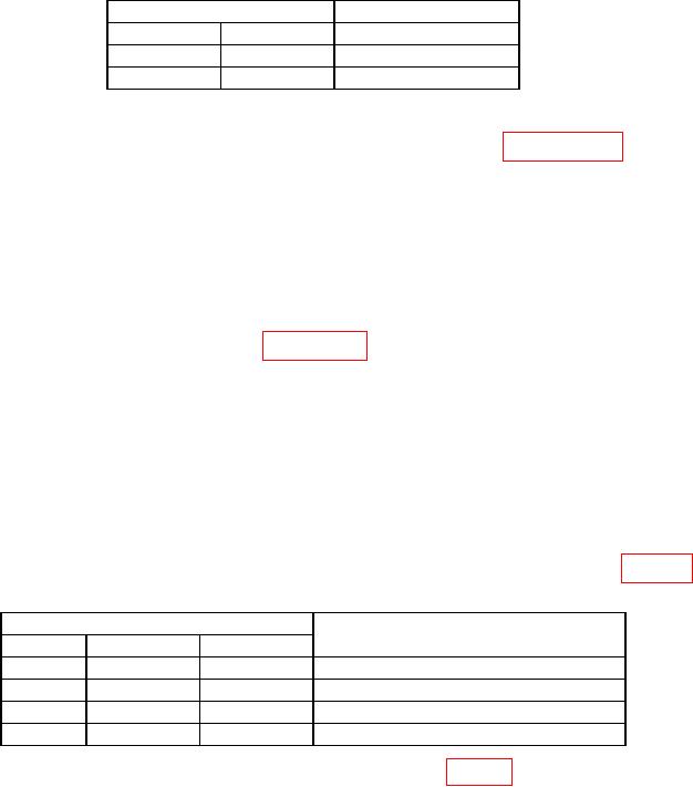
Table 12. Output Jitter.
Test instrument
Function
Frequency
Maximum indication
Square
100 kHz
<0.01%
+ 525 ps
Square
10 MHz
< 0.1%
+ 75 ps
(9) Set Output to off and disconnect equipment.
b. Adjustments. Perform entire alignment procedure listed in paragraph 13.
13. Alignment Procedure
NOTE
If the alignment procedure below has not yet been performed, it
must be done at this time.
NOTE
Press Utility and Test/Cal keys; if Secure On is highlighted,
perform steps outlined in paragraph 7 d through f.
(1) Connect TI Output to frequency counter channel A input. Set counter for a 50 Ω
input on channel A.
(2) Press Utility, Test/Cal, Perform Cal, and BEGIN keys. Wait for internal cal to
complete.
(3) When Setup # 2 is displayed press BEGIN key.
(4) Using numerical keypad, adjust displayed Meas'd Freq to match frequency
counter indication. Press ENTER VALUE key, when values match.
(5) Repeat technique of (3) and (4) above for remaining parameters listed in table 13.
Table 13. Adjustment Setup #2 Through #5.
Test instrument indications
Typical test requirements
Setup #
Frequency
Amplitude
2
<10 MHz
1 Vp-p
Frequency is slightly less than 10 MHz
3
>10 MHz
1 Vp-p
Frequency is slightly more than 10 MHz
4
~10 MHz
1 Vp-p
Frequency should be near 10 MHz
5
10 MHz
1 Vp-p
Frequency should be 10 MHz 1 ppm
(6) Disconnect TI and connect equipment as shown in figure 1 below.
(7) Set multimeter to display 5 digits and DCV measurement.
(8) When Setup # 6 is displayed press BEGIN key.
(9) Using numerical keypad, adjust displayed Meas'd Voltage to match multimeter
indication. Press ENTER VALUE key, when values match.