
TB 9-6625-2327-24
(9) Set TI output frequency and amplitude as listed in table 10. Set output to on.
(10) Set audio analyzer to measure distortion in percent (%).
If audio analyzer
indication is not within limits specified in table 10, perform b below.
(11) Repeat technique of (9) and (10) above for remaining parameters listed in table 10.
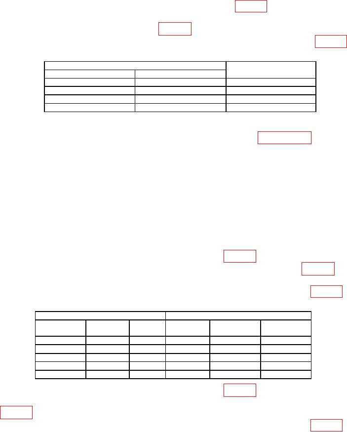
Table 10. Total Harmonic Distortion.
Test instrument settings
Audio analyzer maximum
limit (%)
Frequency (Hz)
Amplitude (Vrms)
100
1
<0.21
19
k
1
<0.21
19
k
3.535
<0.21
100
3.535
<0.21
(12) Set Output to off and disconnect equipment.
b. Adjustments. Perform entire alignment procedure listed in paragraph 13.
12. Output Characteristics
a. Performance Check
(1) Connect TI Output to oscilloscope channel 1 input. Set oscilloscope channel 1
to 50 Ω.
(2) Press TI keys as listed in (a) through (c) below:
(a) Ampl, 1, Vrms.
(b) Utility, Output Setup, Load and Done.
(c) Output on.
(3) Set TI output function and frequency as listed in table 11. Set output to on.
(4) Adjust oscilloscope controls as necessary to verify function listed in table 11. If
measurement is not within limits specified, perform b below.
(5) Repeat technique of (3) and (4) above for remaining parameters listed in table 11.
Table 11. Output Characteristics.
Test instrument
Oscilloscope
Pulse
Function
Function
Min
Max
(Hz)
width
Square
100
k
////
Risetime
////
≤8 ns
Square
100
k
////
Falltime
////
≤8 ns
Square
100
k
////
Overshoot
////
<5%
Square
1
k
////
Duty Cycle
49.5 %
50.5 %
Pulse
1
k
100 uS
Overshoot
////
<5%
(6) Set TI output function and frequency as listed in table 12. Set output to on.
(7) Adjust oscilloscope controls as necessary to verify jitter at settings listed in
table 12. If measurement is not within limits specified, perform b below.
(8) Repeat technique of (6) and (7) above for remaining parameters listed in table 12.