
TB 9-6625-2329-24
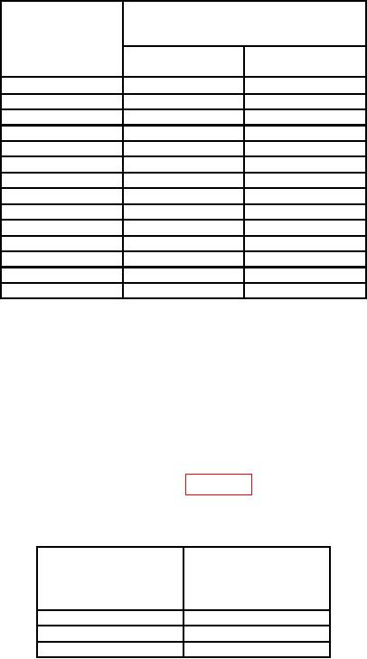
Table 13. Level Accuracy
Test instrument
indications at 1 kHz
DATA and
(ac V)
ENTER/UNITS
(mV)
Min
Max
2
.00098
.00302
6
.00494
.00706
18
.01682
.01918
36
.03464
.03736
64
.06236
.06564
100
.098
.102
130
.1277
.1323
290
.2861
.2939
550
.5435
.5565
1000
.989
1.011
1200
1.187
1.213
1500
1.484
1.516
1750
1.7315
1.7685
2000
1.979
2.021
(9) Press PARAMETERLEVEL pushbutton and press ON/OFFOFF key.
(10) Disconnect TI AF INT from multimeter.
(11) Connect TI AF INT to audio analyzer INPUT HIGH.
(12) Set up audio analyzer to measure distortion.
(13) Press PARAMETER LEVEL pushbutton, enter DATA 1000 numerical value,
and press ENTER/UNITS mV key.
(14) Press TI PARAMETER AF pushbutton, enter DATA numerical value, and
press ENTER/UNITS kHz for each row in table 14. Distortion analyzer will indicate
within limits.
Table 14. Modulation Generator Distortion
Test instrument
DATA and
Audio analyzer
ENTER/UNITS
distortion indications
(kHz)
(<%)
1
0.1
19.2
0.1
99.9
0.1
(15) Press PARAMETER LEVEL pushbutton and press ON/OFFOFF key.
(16) Disconnect TI AF INT audio analyzer INPUT HIGH.
(17) Connect TI AF INT to frequency counter CHANNEL A input.
(18) Set up frequency counter to measure frequency.
(19) Press PARAMETER LEVEL pushbutton, enter DATA 1000 numerical value,
and press ENTER/UNITS mV level key.
16