
TB 9-6625-2330-24
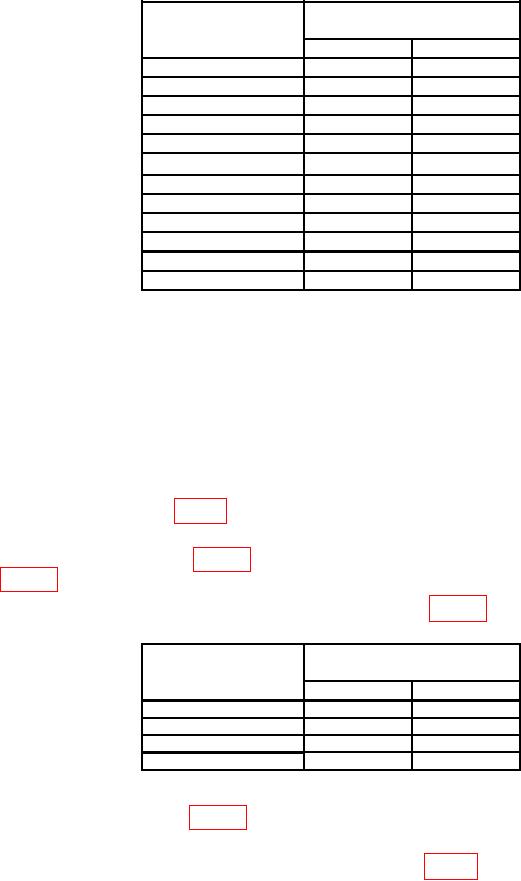
Table 6. 30 MHz RF Output.
Measuring receiver
Test instrument
Indications (dB)
DATA ENTRY
level
Min
Max
0 dBm
-1.5
1.5
-10 dBm
-11.5
-8.5
-20 dBm
-21.5
-18.5
-30 dBm
-31.5
-28.5
-40 dBm
-41.5
-38.5
-50 dBm
-51.5
-48.5
-60 dBm
-61.5
-58.5
-70 dBm
-71.5
-68.5
-80 dBm
-81.5
-78.5
-90 dBm
-91.5
-88.5
-100 dBm
-101.5
-98.5
-110 dBm
-111.5
-108.5
(11) Press TI pushbuttons as listed in (a) through (e) below:
(a) FUNCTION-CARR FREQ.
(b) DATA ENTRY-1300 MHz.
(c) FUNCTION-CARR LEVEL.
(d) DATA ENTRY- 13 dBm.
(e) FUNCTION-RF ON to on (red light lit).
(12) Using RF power measurement techniques, measuring receiver will indicate
within limits specified in table 7 for TI RF power level setting.
(13) Press TI FUNCTION-CARR LEVEL and DATA ENTRY keys to set TI output
level to next value listed in table 7. Measuring receiver will indicate within limits specified
in table 7.
(14) Repeat (13) above for remaining levels listed in table 7.
Table 7. 1300 MHz RF Output.
Measuring receiver
Test instrument
Indications (dB)
DATA ENTRY
level
Min
Max
13 dBm
10.5
15.5
10 dBm
7.5
12.5
5 dBm
2.5
7.5
0 dBm
-2.5
2.5
(15) Press TI FUNCTION-CARR LEVEL and DATA ENTRY keys to set TI output
level to first value listed in table 8.
(16) Using standard tuned level measurement techniques, with tracking option on,
measuring receiver will indicate within limits specified in table 8 for TI RF level setting.
9