
TB 9-6625-2330-24
(f) DATA ENTRY 200 kHz.
(9) Configure measuring receiver to measure FM with a + PEAK detector, no high-
pass filter and no low-pass filter.
(10) Using measuring receiver, measure FM Modulation distortion.
(11) Measuring receiver will indicate within limits specified in table 26.
Table 26. Measuring Receiver Distortion Indications.
Audio analyzer distortion indication
(%)
2
(12) Press TI FUNCTION-CARR FREQ, FUNCTION-MOD LEVEL, and DATA
ENTRY keys for values listed in table 27. Using measuring receiver, measure FM
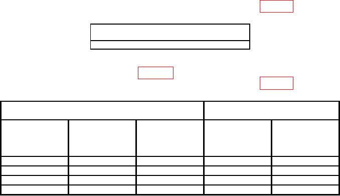
deviation. Measuring receiver will indicate within limits specified in table 27.
Table 27. FM Deviation.
Measuring receiver indications
Test instrument
(kHz )
DATA ENTRY
DATA ENTRY
DATA ENTRY
modulation
Min
Max
carrier frequency
deviation
(MHz)
(kHz)
(kHz)
1050
1
100
90
110
256
1
25
22.5
27.5
50
1
150
135
165
256
1
187
168.3
205.7
b. Adjustments. No adjustments can be made.
18. Phase Modulation
a. Performance Check
(1) Connect measuring receiver sensor module to TI RF OUTPUT.
(2) Press TI pushbuttons as listed in (a) through (j) below:
(a) FUNCTION-CARR FREQ.
(b) DATA ENTRY- 8 MHz.
(c) FUNCTION-CARR LEVEL.
(d) DATA ENTRY- 10 dBm.
(e) FUNCTION-MOD FREQ.
(f) DATA ENTRY- 1 kHz.
(g) FUNCTION-MOD LEVEL.
(h) DATA ENTRY- 10 RAD.