
TB 9-6625-2330-24
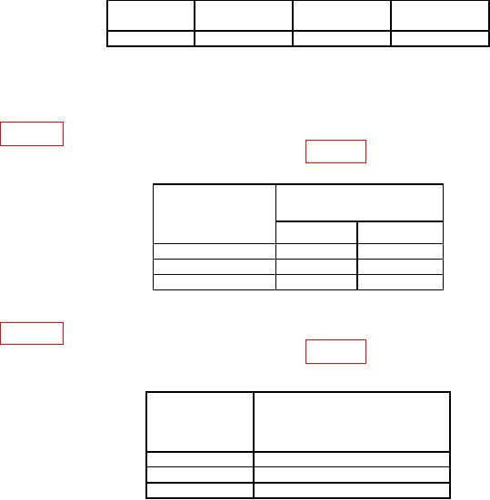
Table 21. Incidental FM.
MOD
Carrier
Modulation
Measuring
FREQ
%
Receiver <Hz
1 GHz
1 kHz
30
200
(5) Configure measuring receiver to measure AM with 15 kHz low-pass filter and a
300 Hz high-pass filter.
(6) Press TI FUNCTION-MOD LEVEL and DATA ENTRY keys for values listed
in table 22. Using measuring receiver, measure AM percent of modulation. Measuring
receiver will indicate within limits specified in table 22.
Table 22. Internal AM Modulation Accuracy.
Test instrument
Measuring receiver
DATA ENTRY
modulation indications (%)
percent of
Min
Max
modulation
30%
23
37
60%
53
67
70%
63
77
(7) Press TI FUNCTION-MOD LEVEL and DATA ENTRY keys for values listed
in table 23. Using measuring receiver, measure AM Modulation distortion. Measuring
receiver will indicate within limits specified in table 23.
Table 23. Measuring Receiver Distortion Indications
Test instrument
Audio analyzer
DATA ENTRY
distortion indications
percent of
(<%)
modulation
30%
3
60%
3
70%
3
b. Adjustments. No adjustments can be made.
17. Frequency Modulation
a. Performance Check
(1) Connect measuring receiver sensor module to TI RF 50 Ohm output.
(2) Press TI pushbuttons as listed in (a) through (i) below:
(a) FUNCTION-CARR FREQ.
(b) DATA ENTRY- 1 GHz.
(c) FUNCTION-CARR LEVEL.
(d) DATA ENTRY- 13 dBm.
(e) FUNCTION-RF ON to on (red light lit).
(f) MODULATION/AUX-MOD SOURCE DISP to SOURCE ONE.