
TB 9-6625-2330-24
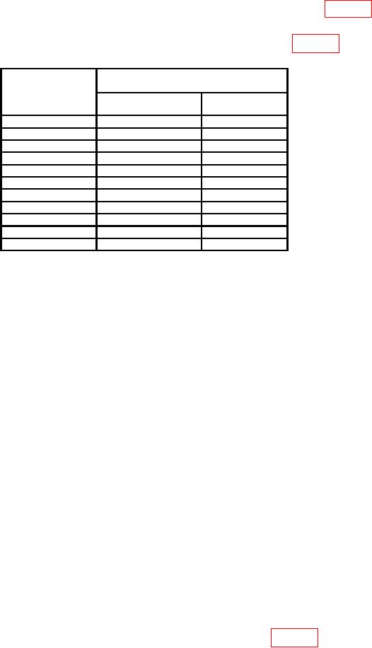
(13) Frequency counter indication will be within limits specified in table 20 for
frequency setting of TI.
(14) Repeat (12) and (13) above for remaining frequencies listed in table 20.
Internal Oscillator Frequency.
Test instrument
Frequency counter indications
DATA ENTRY
(Hz)
mod frequency
Min
Max
settings
1
kHz
0.999
k
1.001
k
0.100 kHz
0.099
k
0.101
k
0.500 kHz
0.499
k
0.501
k
5
kHz
4.999
k
5.001
k
10
kHz
9.999
k
10.001
k
50
kHz
49.999
k
50.001
k
100
kHz
99.999
k
100.001
k
200
kHz
199999
200001
300
kHz
299999
300001
400
kHz
399999
400001
500
kHz
499999
500001
(15) Disconnect TI MODULATION IN/OUT from frequency counter A input.
b. Adjustments. No adjustments can be made.
16. Amplitude Modulation
a. Performance Check
(1) Connect measuring receiver sensor module to TI RF 50 Ohm output.
(2) Press TI pushbuttons as listed in (a) through (j) below:
(a) FUNCTION-CARR FREQ.
(b) DATA ENTRY- 1 GHz.
(c) FUNCTION-CARR LEVEL.
(d) DATA ENTRY- 0 dBm.
(e) FUNCTION- RF ON to on (red light lit).
(f) FUNCTION-MOD FREQ.
(g) DATA ENTRY- 1 kHz.
(h) FUNCTION-AM LEVEL.
(i) DATA ENTRY- 30%.
MODULATION/AUX MOD ON ONE to on (red light lit).
(j)
(3) Configure measuring receiver to measure FM with a 3 kHz low-pass filter and a
300 Hz high-pass filter.
(4) Measuring receiver will indicate within limits specified in table 21.