
TB 9-6625-2337-24
(h) Move the terminator from the output port to the auxillary port and connect
the measuring receiver to the output port.
(i) Record the measuring receiver indication in table 41 for use in (8) below.
(j) Repeat technique in paragraphs (a) through (i) above at 1030 MHz at 0 dB.
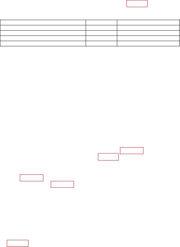
Table 41. Standards Values
Standard
Reading
Directional coupler + 20 dB attenuator
1090 MHz
Input port to output port insertion loss
1090 MHz
Directional coupler + 20 dB attenuator
1030 MHz
Input port to output port insertion loss
1030 MHz
(2) Press TI keys as listed in (a) through (e) below:
(a) Press FUNC, ENTR keys.
(b) Use the arrow keys to highlight GENERAL MENUS and press ENTR key.
(c) 16, ENTR (GENERAL MEASUREMENTS).
(d) Use the arrow keys to highlight TYPE:.
(e) ENTR (CW).
(3) Connect the power amplifier to +13 V output of dc power supply, monitored
with multimeter.
(4) Connect the signal generator to the power amplifier input.
(5) Connect power amplifier output to directional coupler.
(6) Connect the main output of the directional coupler to the TI MAIN RF I/O 1W
TO 10 KW input connector.
(7) Connect the 20 dB sample output of the directional coupler and a 20 dB
attenuator to the measuring receiver.
(8) Compute the measuring receiver indication by algebraically adding the
directional coupler + attenuator value recorded in table 41 above to +40 dB, then
subtracting the insertion loss value recorded in table 41 above from the total.
EXAMPLE
If directional coupler + attenuator value recorded in
table 41 above = -39.33 dB, and the insertion loss value
recorded in table 41 above = -0.32 dB, then the computed
measuring receiver indication would be:
+40 dB + (-39.33 dB) (-0.32 dB) = 0.99 dB
receiver indication equal to the value calculated in (8) above.
(10) Use the arrow keys to highlight POWER and press ENTR key.
(11) Verify the TI measured value displayed on the monitor is +40.0 dBm 0.5 dB.
(12) Repeat technique of (4) through (11) above for remaining settings and limits
listed in table 42.
66