TB 9-6625-2337-24
25. Out Main/Aux
a. Performance Check
NOTE
Verify that the proper CAL FACTORS are loaded for the
measuring receiver power sensor module.
(1) Zero and calibrate the measuring receiver power sensor module.
(2) Connect the measuring receiver power sensor module to TI MAIN RF I/O 1W
TO 10 KW connector.
(3) Set measuring receiver to measure frequency.
(4) Press TI keys as listed in (a) through (i) below:
Press FUNC, ENTR keys.
(a)
Use the arrow keys to highlight GENERAL MENUS and press ENTR key.
(b)
11, ENTR (MAIN MODULATION).
(c)
Use the arrow keys to highlight CW:.
(d)
ENTR (ON).
(e)
Use the arrow keys to highlight AUX:.
(f)
95, ENTR (-95).
(g)
Use the arrow keys to highlight RF:.
(h)
0, ENTR (-0).
(i)
(5) Verify that the measuring receiver indication is approximately 1030 MHz.
(6) Set measuring receiver to measure tuned RF level in log mode.
(7) Verify that the measuring receiver indication is within limits listed in table 40.
(8) Repeat technique of (4) and (7) above for remaining settings and limits listed in
NOTE
CAL and RECAL measuring receiver as necessary.
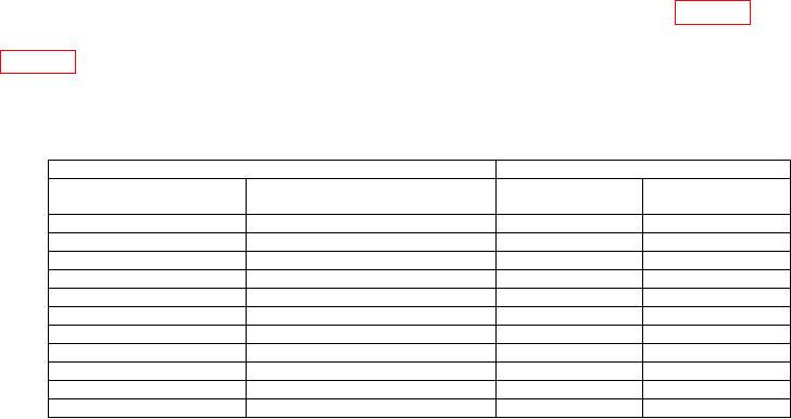
Table 40. Output Power Level
TI
Measuring receiver indication
Test description
Settings
Minimum
Maximum
(dB)
(dB)
MAIN 0 dB @ 1030 MHz
----------------------------------------
-1.0
1.0
10, ENTR (-10)
MAIN -10 dB @ 1030 MHz
-11.0
-9.0
20, ENTR (-20)
MAIN -20 dB @ 1030 MHz
-21.0
-19.0
30, ENTR (-30)
MAIN -30 dB @ 1030 MHz
-31.0
-29.0
40, ENTR (-40)
MAIN -40 dB @ 1030 MHz
-41.0
-39.0
50, ENTR (-50)
MAIN -50 dB @ 1030 MHz
-51.0
-49.0
60, ENTR (-60)
MAIN -60 dB @ 1030 MHz
-61.0
-59.0
70, ENTR (-70)
MAIN -70 dB @ 1030 MHz
-71.0
-69.0
80, ENTR (-80)
MAIN -80 dB @ 1030 MHz
-81.0
-79.0
90, ENTR (-90)
MAIN -90 dB @ 1030 MHz
-91.0
-89.0
95, ENTR (-95)
MAIN -95 dB @ 1030 MHz
-96.0
-94.0

