
TB 9-6625-2340-24
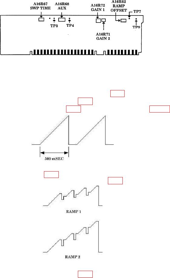
Figure 3. A16 board.
(11) Set oscilloscope to display a 0 to 10 volt sweep ramp using Vertical 2 as the
trigger source.
(12) Adjust A16R67 SWP TIME for a ramp of 500 msec (fig. 4) duration (R).
(13) Disconnect oscilloscope from A16TP3 (fig. 3).
Figure 4. 500 mSec ramp.
(15) Adjust A16R68 AUX (fig. 3) to align the dc level of the rest time between each
ramp with the upper dc level of each ramp. Refer to RAMP 2 (fig. 5).
Figure 5. Ramps.
(16) Disconnect oscilloscope from A16TP4 (fig. 3).
10