
TB 9-6625-2340-24
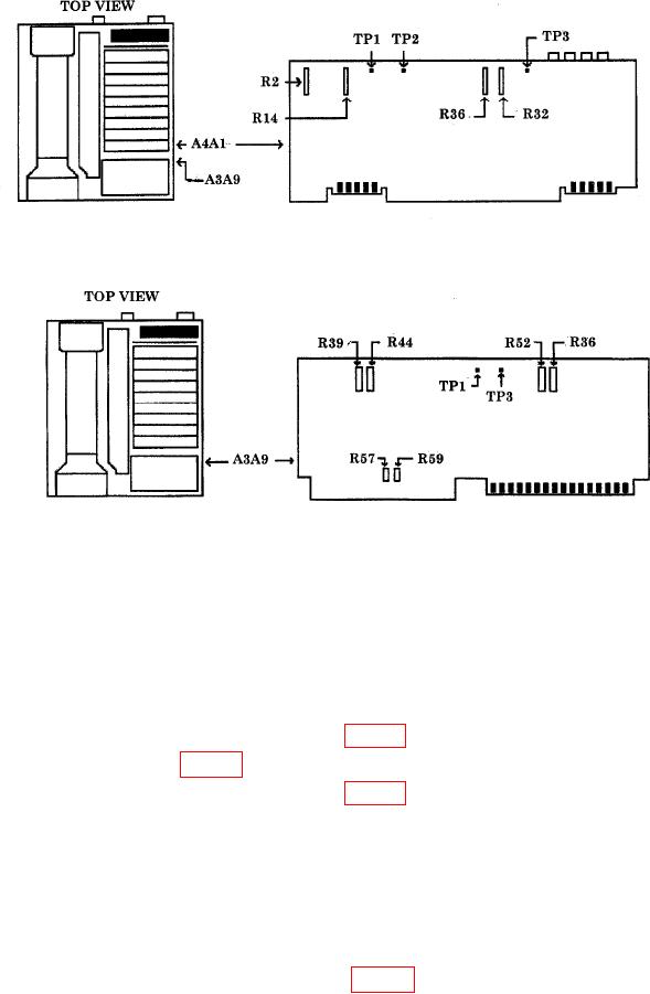
Figure 21. A4A1 board.
Figure 22. A3A9 board.
(10) Press TI keys as listed in (a) through (c) below:
(a) CENTER FREQUENCY, 100, MHz.
(b) FREQUENCY SPAN, 0, Hz.
(c) SCALE LIN.
(11) Set attenuator No. 2 to 120 dB. Multimeter indication should be 0.000 0.001 V dc (R).
(12) Connect multimeter HI to A4A1TP2 (fig. 21).
(13) Adjust A4A1R14 (fig. 21) for a multimeter indication of 5.000 0.003 V dc (R).
(14) Connect multimeter HI to A4A1TP1 (fig. 21).
(15) Set attenuator No. 2 to 0 dB.
(16) Press TI REFERENCE LEVEL key.
(17) Adjust TI DATA knob for a multimeter indication as close to 1.000 0.001 V dc
as possible. (It may be necessary to slightly adjust the TI AMPTD CAL control to achieve
required tolerance).
(18) Press TI SCALE LOG, 1, dBm keys.
(19) Connect multimeter HI to A4A1TP3 (fig. 21) and multimeter LO to chassis.
34