
TB 9-6625-2340-24
(17) Disconnect multimeter from TI.
(18) Position TI on its right side.
(19) Remove TI bottom cover.
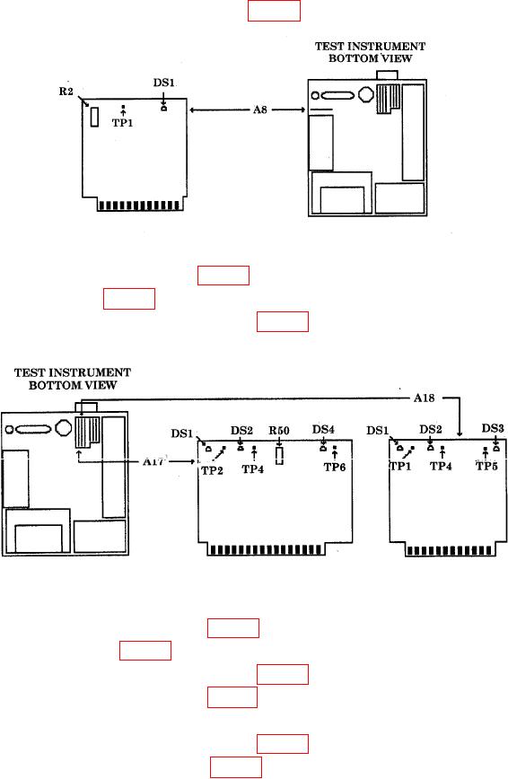
(20) Connect multimeter HI to A8TP1 (fig. 33) and multimeter LO to TI chassis.
Figure 33. A8 board.
(21) The 22 V indicator A8DS1 (fig. 33) (yellow LED) should be lit.
(22) Adjust A8R2 (fig. 33) for a multimeter indication of 22.000 0.020 V dc (R).
(23) Connect multimeter HI to A17TP4 (fig. 34) and multimeter LO to TI chassis.
Figure 34. A17 & A18 boards.
(24) The 20 V indicator A17DS2 (fig. 34) (yellow LED) should be lit.
(25) Adjust A17R50 (fig. 34) for a multimeter indication of 20.000 0.001 V dc (R).
(26) Connect multimeter HI to A17TP6 (fig. 34) and multimeter LO to TI chassis.
(27) The 12 V indicator A17DS4 (fig. 34) (yellow LED) should be lit.
(28) Multimeter should indicate 12.25 0.30 V dc.
(29) Connect multimeter HI to A17TP2 (fig. 34) and multimeter LO to TI chassis.
(30) The 5.2 V indicator A17DS1 (fig. 34) (yellow LED) should be lit.
81