
TB 9-6625-2340-35
(2) Set TI LINE switch to STANDBY.
(3) Position TI on its right side.
(4) Remove TI bottom cover.
(5) Remove cover over A12 through A16 pc boards.
(6) Jumper A12TP2 to A12TP3 (lock indicator disable).
(7) Set TI LINE switch to ON.
(8) Press 0 2.5 GHz, SWEEP TIME, 500, mS.
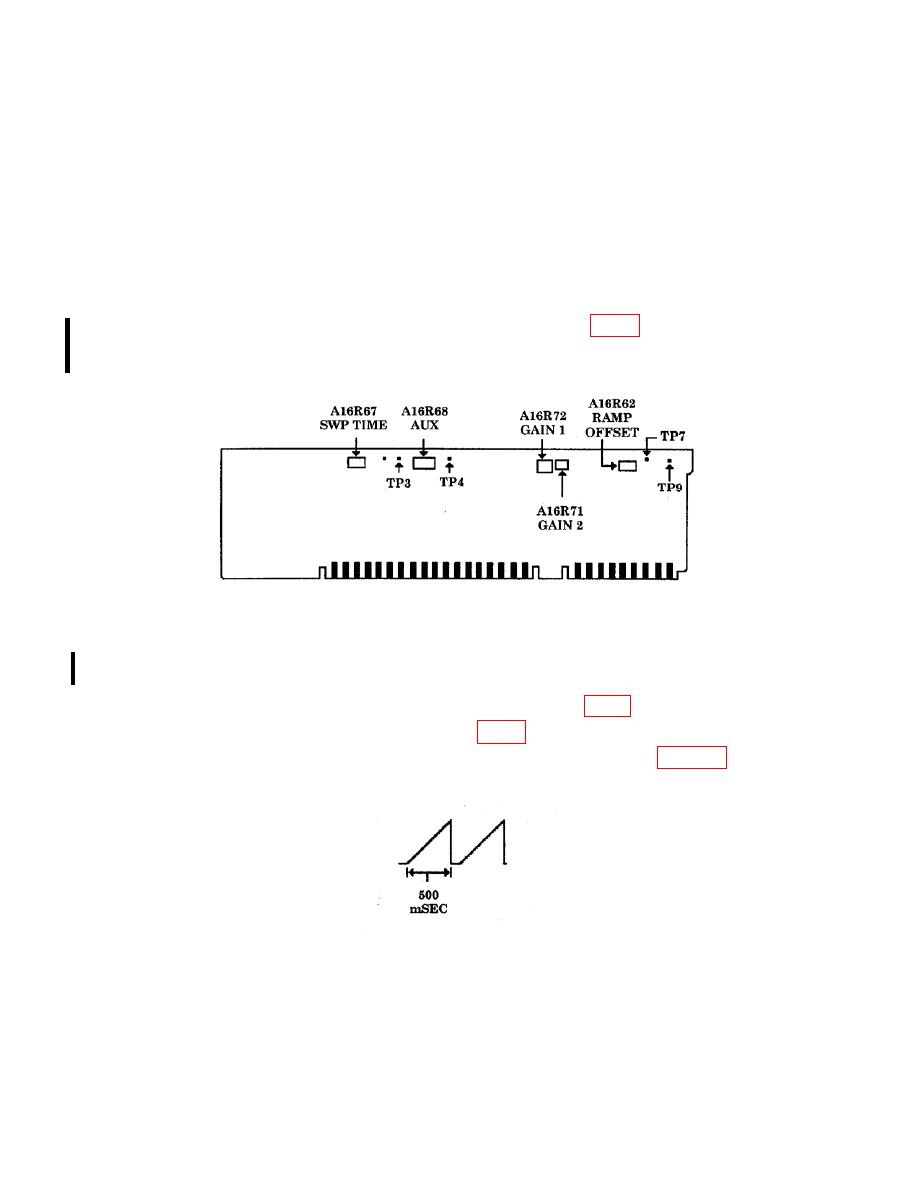
(9) Connect oscilloscope Vertical 1 input to TI A16TP3 (fig. 3).
(10) Connect TI SWEEP + TUNE OUT (rear panel) to oscilloscope Vertical 2 input.
(11) Set oscilloscope to display a 0 to 10 volt sweep ramp using Vertical 2 as the
trigger source.
(12) Adjust A16R67 SWP TIME for a ramp of 500 msec (fig. 4) duration (R).
(13) Disconnect oscilloscope from A16TP3 (fig. 3).
(14) Connect oscilloscope to A16TP4. Display should be similar to figure 4.
