
TB 9-6625-2340-35
(15) Adjust A16R68 AUX (fig. 3) to align the dc level of the rest time between each
ramp with the upper dc level of each ramp. Refer to RAMP 2 (fig. 5).
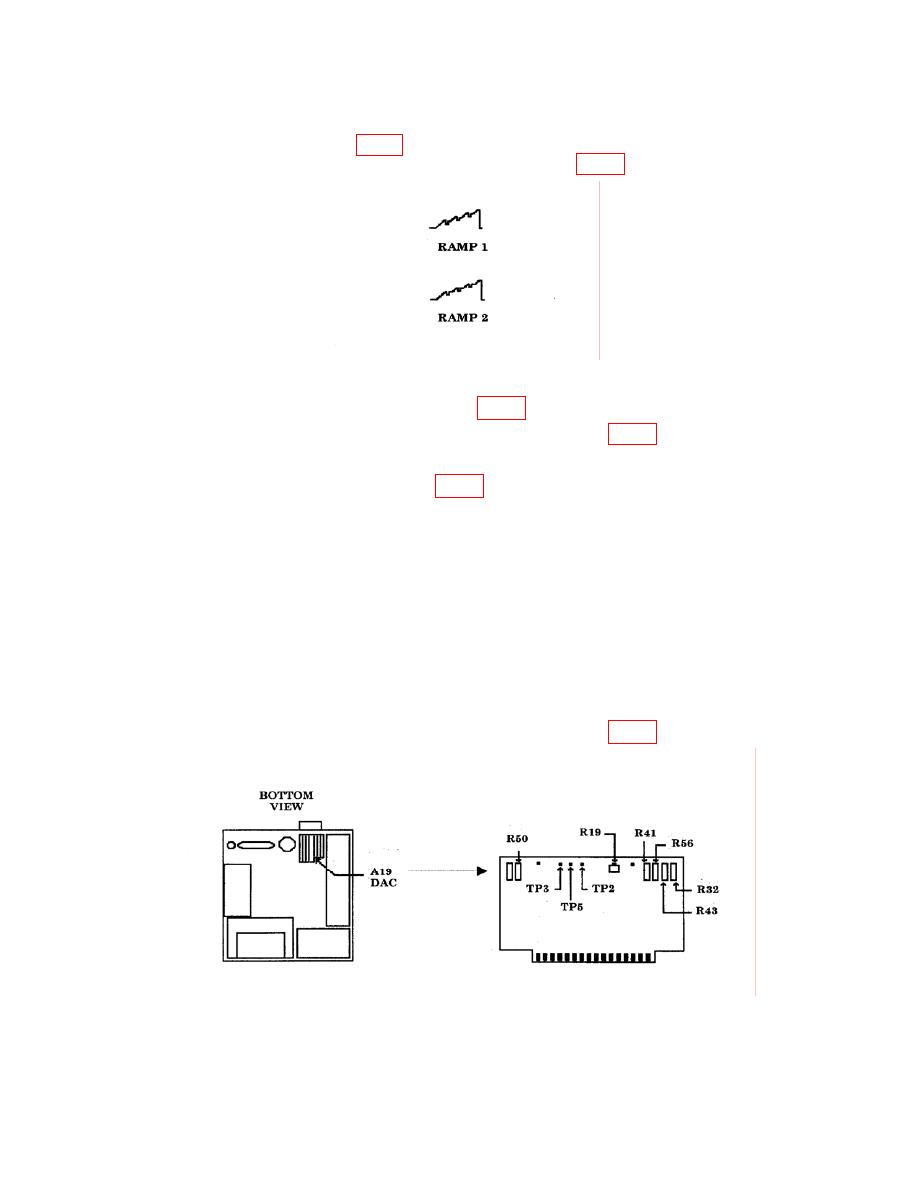
Figure 5. Ramps.
(16) Disconnect oscilloscope from A16TP4 (fig. 3).
(17) Connect multimeter HI to A16TP9 and LO to A16TP7 (fig. 3).
(18) Press TI SWEEP SINGLE key.
(19) Adjust A16R62 RAMP OFFSET (fig. 3) for a multimeter indication as close to
0.000 V dc as possible.
(20) Repeat steps (18) and (19) until requirement is met.
(21) Press TI keys as listed in (a) through (g) below:
(a)
SWEEP SINGLE.
(b)
START FREQ, 2.5, GHz.
(c)
STOP FREQUENCY, 4.9, GHz.
SHIFT, MKR→REF LVL.
(d)
(e)
SAVE, 1.
(f)
STOP FREQ, 2.51, GHz.
(g)
SAVE, 2.
(22) Connect multimeter HI to A19TP2 and LO to A19TP3 (fig. 6).
11
