
TB 9-6625-2346-35
(k) A TRIGGER A SOURCE switch to INT.
(l) A TRIGGER A EXT COUPLING switch to DC.
(2) Connect oscilloscope calibrator SOURCE/MEASURE CHAN 1 to TI CH 1
input and oscilloscope calibrator SOURCE/MEASURE CHAN 2 to TI CH 2 input using
50Ω feed through terminations.
(3) Set oscilloscope calibrator for a SOURCE/MEASURE CHAN 1, LEVEL SINE
output of 10 MHz and 3.5 divisions of vertical display on TI.
(4) Set TI CH 1 VOLTS/DIV switch to 50m.
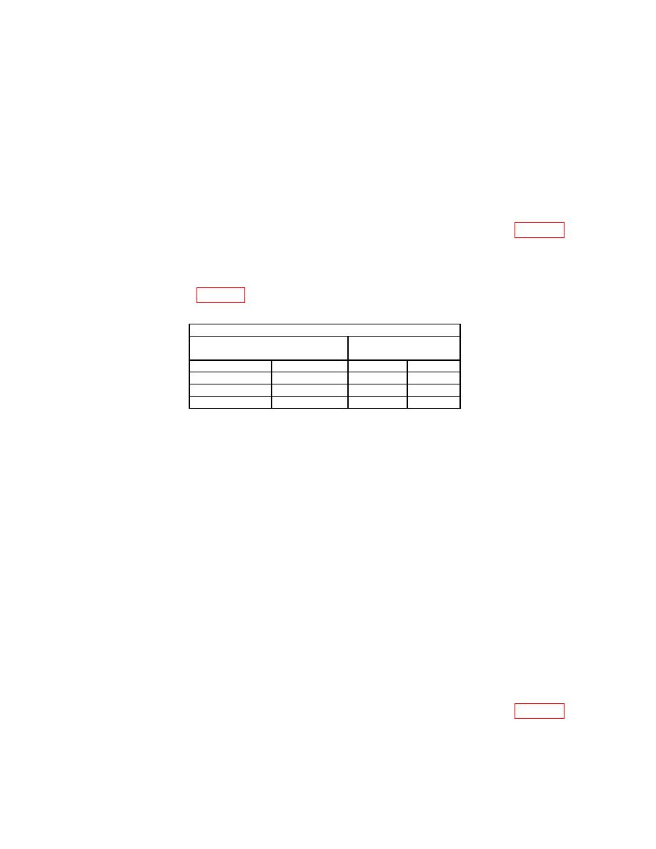
(5) Set TI A TRIGGER pushbuttons to combination listed in first row of table 15.
(6) Adjust TI A TRIGGER LEVEL control to obtain a stable display. If a stable
display cannot be obtained perform b below.
(7) Repeat technique of (5) and (6) above for remaining A TRIGGER pushbutton
combinations listed in table 15. If a stable display cannot be obtained perform b below.
Test instrument
A TRIGGER pushbutton
A TRIGGER LEVEL
stable display
MODE
SLOPE
YES
NO
NORM
IN:
P-P AUTO
IN:
P-P AUTO
OUT:
(8) Set TI HORIZONTAL MODE A ALT B switch to B. Adjust B INTENSITY
control for suitable viewing.
(9) Verify a stable display can be obtained by adjusting B TRIGGER LEVEL
control in a position other than B RUNS AFTER DLY; if not, perform b below.
(10) Press TI B TRIGGER SLOPE pushbutton to IN and verify a stable display can
be obtained by adjusting B TRIGGER LEVEL control in a position other than B RUNS
AFTER DLY; if not, perform b below.
(11) Position controls as listed in (a) through (d) below:
(a)
VERTICAL MODE CH1 BOTH CH2 switch to CH 2.
(b)
HORIZONTAL MODE A ALT B switch to A.
(c)
B TRIGGER SLOPE pushbutton to OUT.
(d)
A TRIGGER A SOURCE switch to CH 2.
NOTE
Ensure TI CH 2 VOLTS/DIV is set to 5m.
(12) Set oscilloscope calibrator for a SOURCE/MEASURE CHAN 2, LEVEL SINE
output of 10 MHz and 3.5 divisions of vertical display on TI.
(13) Set TI CH 2 VOLTS/DIV switch to 50m.
(14) Set TI A TRIGGER pushbuttons to combination listed in first row of table 16.
(15) Adjust TI A TRIGGER LEVEL control to obtain a stable display. If a stable
display cannot be obtained perform b below.
22
