
TB 9-6625-2347-35
(7) Set oscilloscope calibrator output to standby.
(8) Set TI VERTICAL MODE CH 1 BOTH CH 2 switch to CH 2 and CH 2
VOLTS/DIV switch to 2m.
(9) Set oscilloscope calibrator CH 2 for a VOLTAGE output of 10 mV at 1 kHz.
(10) Adjust TI TRIGGER LEVEL and POSITION controls, as necessary, to view
(11) Rotate oscilloscope calibrator knob located below EDIT FIELD key for 5
divisions of vertical display. If oscilloscope calibrator Err display does not indicate within
limits specified in first row of table 4, perform b below.
(12) Repeat technique of (8) through (11) above for settings listed in table 4. If
oscilloscope calibrator err display does not indicate within limits specified in table 4,
perform b below.
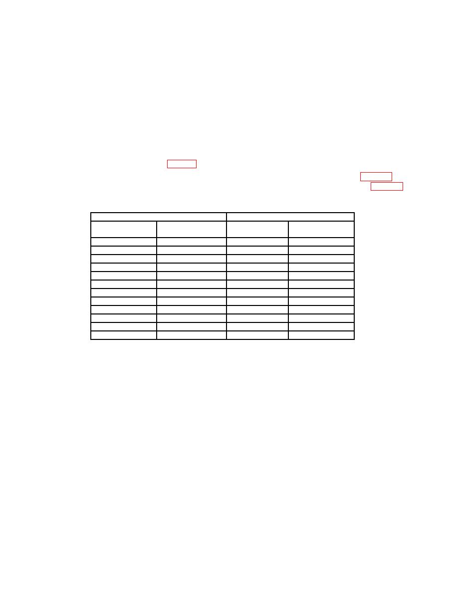
Test instrument
Oscilloscope calibrator
VOLTS/DIV
Divisions of vertical
VOLTAGE
Err display
setting
deflection
output
Indication (%)
2m
5
10 mV
3
5m
4
20 mV
3
10 m
5
50 mV
3
20 m
5
.1 V
3
50 m
4
.2 V
3
.1 V
5
.5 V
3
.2 V
5
1V
3
.5 V
4
2V
3
1V
5
5V
3
2V
5
10 V
3
5V
4
20 V
3
10 V
5
50 V
3
(13) Set oscilloscope calibrator output to standby.
(14) Connect oscilloscope calibrator SOURCE/MEASURE CHAN 1 through a 50Ω
feed through termination to TI CH 1 input and oscilloscope calibrator
SOURCE/MEASURE CHAN 2 through a 50Ω feed through termination to TI CH 2 input.
(15) Position TI switches as listed in (a) through (c) below:
(a) VERTICAL MODE CH 1 BOTH CH 2 to CH 1.
(b) CH 1 and CH 2 VOLTS/DIV to 2m.
(c) SEC/DIV to 20 s.
(16) Set oscilloscope calibrator for a CHAN 1, LEVEL SINE mode output of 12 mV
at a frequency of 50 kHz.
(17) Rotate oscilloscope calibrator knob below EDIT FIELD pushbutton to adjust
amplitude for 6 divisions of deflection on TI.
6
