
TB 9 6625-357-24
k. Adjust P206 (fig. 1) for minimum dc voltage indication on multimeter while turning
CUTOFF FREQ Hz dial from 200 to 20.
l. Repeat f and h above.
8. Noise Level and Stability
NOTE
Perform paragraphs 16 through 19, using left section and then
repeat for right section.
a. Performance Check
(1) Set CUTOFF FREQ Hz dial to 20 and selector switch to HIGH PASS X1.
(2) Short INPUT connector.
(3) Connect multimeter to OUTPUT connector.
Noise level, as indicated on
multimeter, will not exceed 150 V ac.
NOTE
All TI covers must be in place. It may be necessary to use
isolation plug on multimeter.
(4) Repeat (3) above with autotransformer output settings of 105 and 125 V.
(5) Return autotransformer output setting to 115 V.
b. Adjustments. No adjustments can be made.
9. Low Pass Dial Accuracy and Unity Gain
a. Performance Check
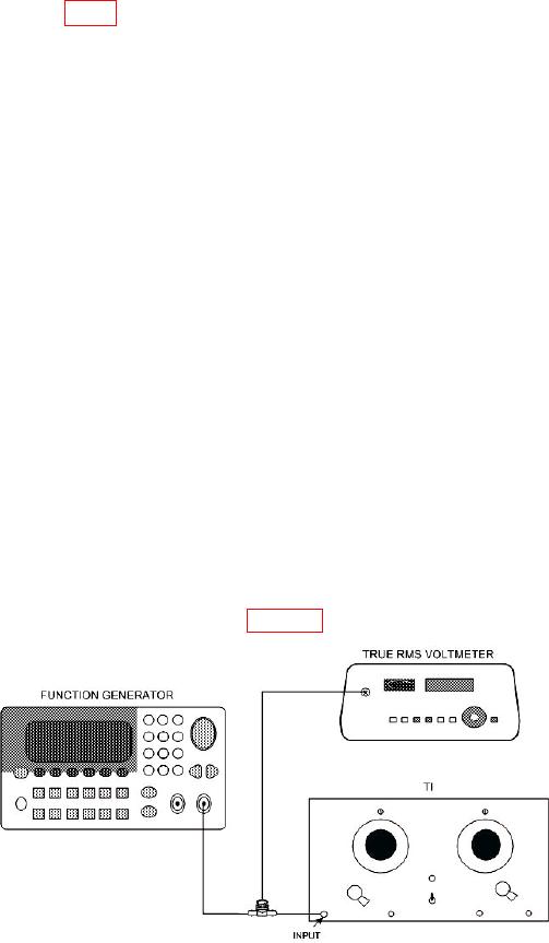
(1) Connect equipment as shown in figure 2, using termination.
Figure 2. Unity gain check - equipment setup.