TB 9-6625-357-24
(2) Set CUTOFF FREQ Hz dial to 35 and selector switch to LOW PASS X10K.
(3) Adjust function generator frequency to 5000 Hz and amplitude to 1 V as
indicated on true rms voltmeter.
(4) Move true rms voltmeter connection from INPUT to OUTPUT. If true rms
voltmeter does not indicate between 0.94 and 1.06 V, perform b (1) below.
(5) Set CUTOFF FREQ Hz dial to 100 and selector switch to HIGH PASS X1. If
true rms voltmeter does not indicate between 0.94 and 1.06 V, perform b (2) below.
(6) Connect frequency counter to INPUT connector.
(7) Set CUTOFF FREQ Hz dial to 60 and selector switch to LOW PASS X100.
(8) Adjust function generator frequency to 600 Hz and amplitude for 1 V indication
on true rms voltmeter.
(9) Set selector switch to LOW PASS X10.
frequency counter does not indicate between 1.5873 and 1.7543 ms, perform b (3) below.
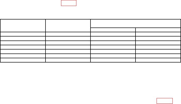
(11) Repeat technique of (7) through (10) above, using TI dial settings and function
generator frequencies listed in table 3. If frequency counter does not indicate within limits
specified, perform b (3) below.
Table 3. Frequency Dial Tracking
Test instrument
Function generator
Frequency counter indications
CUTOFF FREQ Hz
frequency
(ms)
dial settings
(Hz)
Min
Max
20
200
4.7619
5.2632
30
300
3.1746
3.5087
40
400
2.3809
2.6316
80
800
1.1904
1.3158
100
1000
0.95238
1.0526
140
1400
1330 Hz
1470 Hz
200
2000
1900 Hz
2100 Hz
(12) Set CUTOFF FREQ Hz dial to 60 and selector switch to LOW PASS X10K.
(13) Adjust function generator frequency to 60 kHz and amplitude until true rms
voltmeter indicates 1 V.
(14) Adjust function generator frequency until true rms voltmeter indicates 0.708 V.
If frequency counter does not indicate between 540 and 660 kHz, perform b (4) and (5) below.
(15) Repeat technique of (12) through (14) above at settings listed in table 4. If
frequency counter does not indicate within limits specified, perform b (6) through (10) below.
6

