
TB 9-6625-381-24
standard and TI. Where the four-to-one ratio cannot be met, the four-to-one accuracy of the
equipment selected is shown in parenthesis.
5. Accessories Required. The accessories required for this calibration are common
usage accessories, issued as indicated in paragraph 4 above, and are not listed in this
calibration procedure.
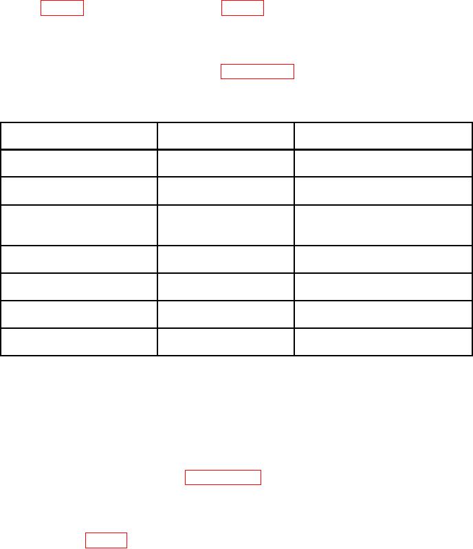
Table 2. Minimum Specifications of Equipment Required
Manufacturer and model
Common name
Minimum use specifications
(part number)
AUTOTRANSFORMER
Range: 0 to 150 Vac
Ridge, Model 9020A (9020A)
Accuracy: 1 Vac
Range: 100 pF to 1.4 F
CAPACITANCE STANDARD
Arco, Model SS32 (7907233)
Accuracy: 1.25%
Hewlett-Packard, Model 3458A
Range: 18.2 to 618 V dc
(3458A)
0 to 50 V ac
Accuracy: 0.75%
Range: 0 to 1 MΩ
RESISTANCE STANDARD
Biddle-Gray, Model 71-631 (7910328)
Accuracy: 1
No.1
Range: 1 to 10 MΩ
Beckman, Model CR10M (8598965)
RESISTANCE STANDARD
Accuracy: 1
No.2
Range: 10 to 100 MΩ
Beckman, Model CR100M (8598966)
RESISTANCE STANDARD
Accuracy: 1
No.3
Range: 100 to 1000 MΩ
Beckman, Model CR1000M (8579478)
RESISTANCE STANDARD
Accuracy: 1
No.4
accuracy of any two 5%.
1Combined
CALIBRATION PROCESS
6. Preliminary Instructions
a. The instructions outlined in paragraphs 6 and 7 are preparatory to the calibration
process. Personnel should become familiar with the entire bulletin before beginning the
calibration.
b. Items of equipment used in this procedure are referenced within the text by common
name as listed in table 2.
c. Unless otherwise specified, verify the result of each test and, whenever the test
requirement is not met, take corrective action before continuing with the calibration.
Adjustments required to calibrate the TI are included in this procedure. Additional
maintenance information is contained in the manufacturer's manual.
d. Unless otherwise specified all controls and control settings refer to the TI.