
TB 9-6625-381-24
(13) Repeat technique of (4) above, using 0.05 F capacitance standard.
(14) Turn DIAL CONTROL throughout its range while observing digital voltmeter.
Indication on multimeter will not exceed 10 V ac. Disconnect multimeter.
(15) Adjust DIAL CONTROL and PERCENT POWER FACTOR control for
minimum indication on TI meter. Dial drum indication will be between 0.047 and 0.053 F.
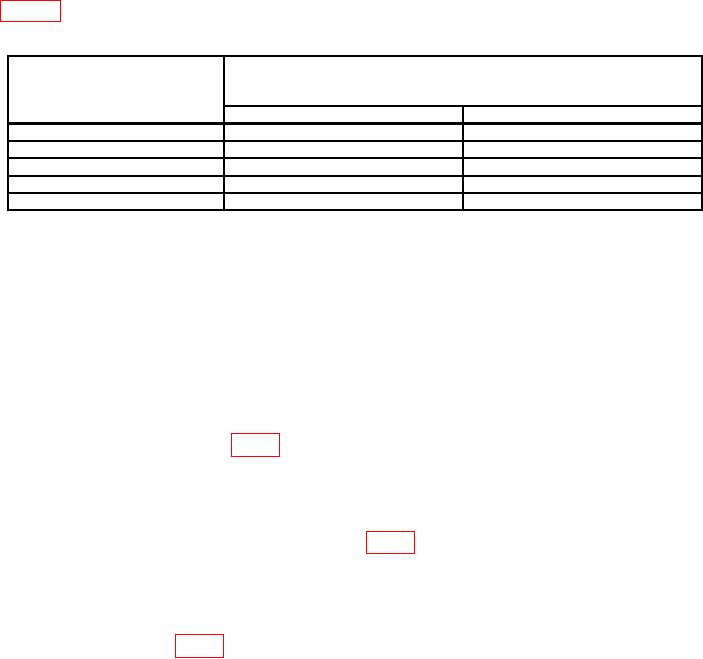
(16) Repeat technique of (15) above, using capacitance standard values listed in
table 4. Dial drum indications will be within limits specified.
Table 4. .04 to 30 MF Range
Capacitance
Test instrument
standard
dial drum indications
(F)
(F)
Min
Max
0.20
0.19
0.21
0.4
0.38
0.42
0.7
0.665
0.735
1.0
0.95
1.05
1.4
1.33
1.47
(17) Connect resistance standard No. 1 and 1 F capacitance standard in series with
capacitance binding posts.
(18) Adjust resistance standard No. 1 to 500 Ω.
(19) Adjust DIAL CONTROL and PERCENT POWER FACTOR control for
minimum indication on TI meter. Indication on PERCENT POWER FACTOR control
will be between 26.5 and 33.5.
b. Adjustments
(1) Remove dust cover from TI.
(2) Turn rotor of C19 (fig. 2) to midrange.
(3) Connect 100 pF capacitance standard to TI capacitance binding posts.
(4) Turn capacitance range switch to 5 TO 100 MMF and turn DIAL CONTROL
to 100 F.
(5) Unlock set screws of capacitors C12 (fig. 2).
(6) Adjust C12 shaft for minimum indication on TI meter (R).
(7) Disconnect capacitance standard from TI.
(8) Set DIAL CONTROL to 0.
(9) Adjust C19 (fig. 2) for minimum indication on TI meter (R).
(10) Repeat technique of (3) through (9) above until minimum indications are
obtained on TI meter at both 100 F and 0 settings of DIAL CONTROL.
(11) On opposite end of tuning indicator drum, from drive wheel's (top side), there is
a screw in a curved slot. Loosen screw (R16, tuning resistor) and slide in curved slot to
adjust. Repeat steps 9 a (1) through (6).
7