
TB 9-6625-952-24
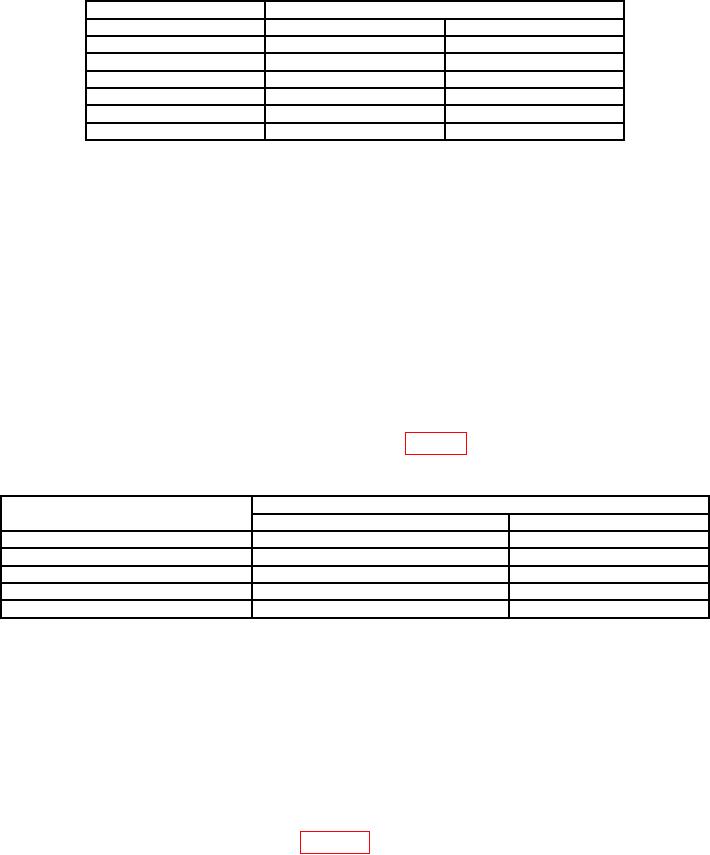
Table 4. AC Voltmeter Check
TI
Ac voltmeter indication (vac)
(V ac)
Minimum
Maximum
10
9.4
10.6
14
13.4
14.6
18
17.4
18.6
22
21.4
22.6
26
25.4
26.6
30
29.4
30.6
(5) Turn TI INCREASE SPEED control to DRIVE POWER OFF.
b. Adjustments. No adjustments can be made.
9. RPM Indicator
a. Performance Check
(1) Connect frequency counter to TI pins C (ground) and A (high) of MAST GEN
OUTPUT connector.
(2) Adjust MAST GEN OUTPUT control until VOLTS RMS meter indicates 5 volts.
Adjust as necessary to maintain this approximate voltage throughout RPM indicator check.
(3) Set the INCREASE SPEED control to DRIVE POWER ON.
Adjust
INCREASE SPEED control for indication of 600 RPM on TI RPM X1 indicator.
Frequency counter will indicate between 98.367 and 101.698 milliseconds.
(4) Repeat (3) above using settings listed in table 5. Frequency counter indications
will be within limits specified.
Table 5. RPM Indicator Check
TI
Frequency counter indication (ms)
RPM setting
Minimum
Maximum
1200
49.588
50.421
2100
28.436
28.708
3200
18.691
18.809
4200
14.251
14.319
5000
11.976
12.024
(5) Adjust INCREASE SPEED control for an RPM X1 indication of 2100. RPM
X2 indication will be 4200. PERCENT RPM indication will be 50% 0.2%.
(6) Turn INCREASE SPEED control to DRIVE POWER OFF.
b. Adjustments. Remove cap on INDICATOR ADJUST and adjust potentiometer as
required to obtain desired RPM indication.
10. Generator Units, 2 and 4 Pole Generator Pads
a. Performance Check
(1) Connect equipment as shown in figure 2.