
TB 9-6625-952-24
(4) Adjust INCREASE SPEED control for indication of 600 RPM on RPM X1
indicator. Frequency counter will indicate a period measurement between 98.367 and
101.698 milliseconds.
(5) Repeat (4) above using settings listed in table 4. Frequency counter indications
will be within limits specified.
(6) Remove phototube reflector adapter from 2 POLE GEN PAD and mount in 4
POLE GEN PAD.
(7) Repeat (4) above at RPM X1 indications as listed in table 6. Frequency counter
will indicate within limits specified.
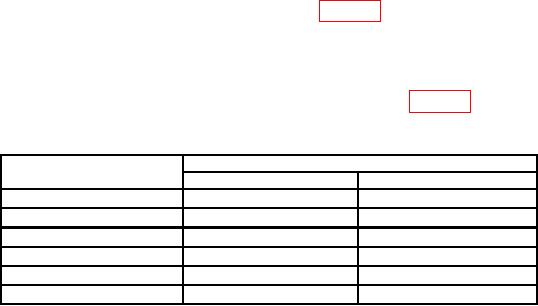
Table 6. RPM Indicator Check (4 pole)
Unit under test
Frequency counter indication (ms)
RPM setting
Minimum
Maximum
600
196.734
203.396
1200
99.176
100.842
2100
56.872
57.414
3200
37.382
37.612
4200
28.502
28.638
5000
23.952
24.048
b. Adjustments. No adjustments can be made.
11. Final Procedure
a. Deenergize and disconnect all equipment.
b. Annotate and affix DA label/form in accordance with TB 750-25.
7/(8 Blank)