
TB 9-6625-102-24
11. AC Current Accuracy
a. Performance Check
(1) Move connection at the TI from the 10 A input to the 440 mA input and from
amplifier Current Output HI and LO to calibrator AUX OUTPUT HI and LO.
(2) Set the TI as listed in (a) through (c) below:
(a) Set rotary switch to
A.
(b) Press SHIFT key for a
indication.
(c)
Press the RANGE key to the 500 A range.
(3) Set the calibrator for AUX Current Output and set the calibrator AC current and
frequency output to the first values in table 8.
(4) TI will indicate within the limits of table 8; if not, perform b below.
(5) Repeat technique of (2)(c) through (4) above for remaining TI ranges and
calibrator AC current and frequency output values in table 8.
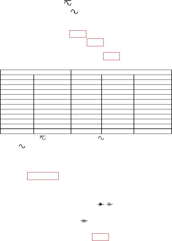
Table 8. AC Current.
TI
Calibrator
Current (A ac)
Frequency (kHz)
Range (A ac)
Min (A ac)
Max (A ac)
500 uA
1
500 uA
496.30 uA
503.70 uA
500 uA
10
500 uA
496.05 uA
503.95 uA
5000 uA
1
5000 uA
4963.0 uA
5037.0 uA
5000 uA
10
5000 uA
4960.5 uA
5039.5 uA
1
50 mA
1
50 mA
49.630 mA
50.370 mA
50 mA
10
50 mA
49.605 mA
50.395 mA
400 mA
0.45
440 mA
395.80 mA
404.20 mA
400 mA
1
440 mA
397.00 mA
403.00 mA
2
5A
1
5A
4.9630 A
5.0370 A
3A
5
5A
2.9040 A
3.0960 A
10 A
1
10 A
9.9100 A
10.0900 A
Set rotary switch to
mA A and press SHIFT key to
.
1
Set output to STBY and move connection at the TI from the 440 mA to the 10 A input, press SHIFT
2
key to
and move the calibrator AUX Current Output HI and LO to the amplifier CURRENT
OUTPUT HI and LO.
(6) Set calibrator output to minimum and disconnect equipment set-up.
b. Adjustments. Perform entire calibration procedure before performing alignment
procedure listed in paragraph 17.
12. Temperature Accuracy
a. Performance Check
ΩTEMPVmV and COM inputs.
(1) Connect calibrator HI and LO output to TI
(2) Configure the TI as listed in (a) and (b) below:
(a) Set rotary switch to TEMP
.
(b)
Press SHIFT and RANGE keys for a C indication.
(3) Set the calibrator to the first value in table 9.

