
TB 9-6625-102-24
(2) Set the TI as listed in (a) through (c) below:
(a) Set rotary switch to TEMP
.
(b) Press the RANGE key to the 10 nF range.
(c) Press the NULL key.
(3) Set the Capacitance Standard to the first value in table 13.
(4) TI will indicate within the limits of table 13; if not, perform b below.
(5) Repeat technique of (2)(b), 3 and (4) above for remaining capacitance standard
values and TI range settings in table 13.
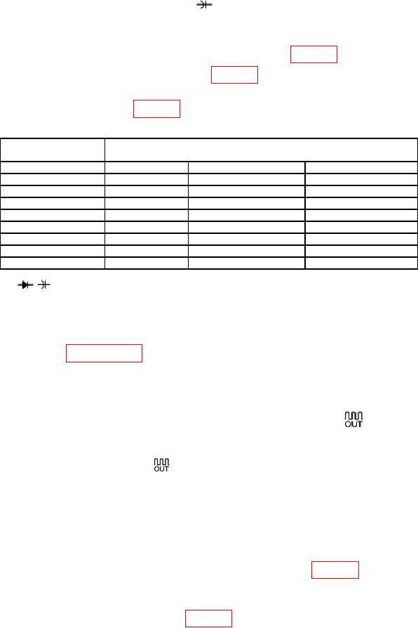
Table 13. Capacitance.
Capacitance
TI
Standard
(F)
Range
Min
Max
10 n
10 nF
9.892 nF
10.108 nF
100 n
100 nF
98.95 nF
101.05 nF
1000 n
1000 nF
989.5 nF
1010.5 nF
10 1
10 F
9.895 F
10.105 F
100 2
100 F
-1.05 F
+1.05 F
1000
1000 F
-10.5 F
+10.5 F
10 m
10 mF
-0.105 mF
+0.105 mF
10 m
100 mF
-0.4 mF
+0.4 mF
Disconnect Capacitance Standard No.1 and connect Capacitance Standard No.2 to TI COM and
1
ΩTEMPVmV inputs.
2 Remaining ranges will be within specified limits of the capacitance standard test reported value.
(6) Set capacitance standard output to minimum and disconnect equipment set-up.
b. Adjustments. Perform entire calibration procedure before performing alignment
procedure listed in paragraph 17.
16. Square Wave Out Accuracy
a. Performance Check
(1) Connect frequency counter CHANNEL 1 input to TI A mA CHG
and COM inputs.
(2) Set the TI as listed in (a) through (d) below:
% ms.
(a) Set rotary switch to
(b) Press SHIFT key for a % indication.
(c) Press the ◄Hz► keys for 120 Hz.
(d) Press ▲ms%▼ keys for 50.000%.
(3) Set the frequency counter to measure frequency on CHANNEL 1.
(4) Frequency counter will indicate within the limits of table 14; if not, perform b
below.
(5) Repeat technique of (2)(c) through (4) above for remaining TI and frequency
counter measurement type and values in table 14.

