
TB 9-6625-2233-35
(e)
ENTER.
(f)
AMPLITUDE.
(g)
.099.
(h)
ENTER.
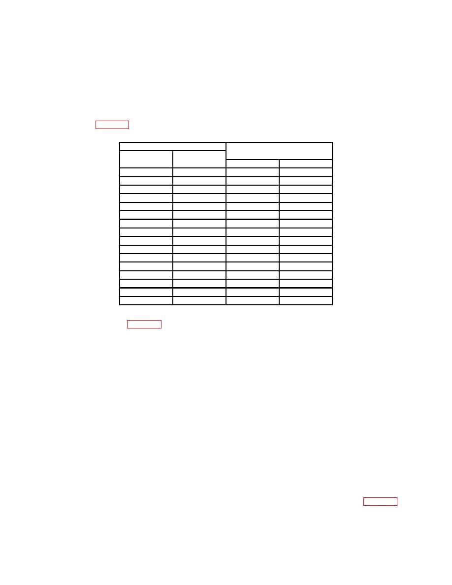
(10) Measuring receiver power meter will indicate within minimum maximum limits
as listed in table 10.
Test instrument
Measuring receiver indications
(mV)
Output
(Hz)
(V p-p)
Min
Max
100
k
.099
26.28
30.87
100
k
.1
26.27
31.47
100
k
.999
272.8
304.0
100
k
1
271.4
306.0
999.9
k
.099
26.28
30.87
999.9
k
.1
26.27
31.47
999.9
k
.999
272.8
304.0
999.9
k
1
271.4
306.0
1
M
.099
26.00
31.16
1
M
.1
25.98
31.75
1
M
.999
270.0
306.8
1
M
1
268.5
308.9
4.999 M
.099
26.00
31.16
4.999 M
.1
25.98
31.75
4.999 M
.999
270.0
306.8
4.999 M
1
268.5
308.9
(11) Repeat technique of (9) (a) through (h) and (10) above substituting settings and
indications listed in table 10.
(12) Reduce TI output to minimum. Disconnect UNBALANCED output from
measuring receiver power sensor and connect UNBALANCED output to oscilloscope
Vertical 1 input using a 50 Ω feedthrough termination.
(13) Press pushbuttons as listed in (a) through (h) below:
(a)
(b)
1.
(c)
EXP.
(d)
6.
(e)
ENTER.
(f)
AMPLITUDE.
(g)
9.99.
(h)
ENTER.
(14) Set oscilloscope Vertical 1 inputs for DC Coupling, 1MΩ Input, scaling for
approximately 4 or 5 divisions displayed, sweep speed for approximately 4 or 5 cycles
displayed and volts pk-pk measurement.
(15) Oscilloscope will indicate within minimum maximum limits as listed in table 11.
20

