
TB 9-6625-2239-35
8. Vertical Deflection
a. Performance Check
(1) Adjust CH 1 POSITION control to align trace on center horizontal graticule line.
(2) Set CH 1 VOLTS/DIV switch to 20 m (10 m for AN/USM-425(V)l). If trace does
not remain aligned with center horizontal graticule line, perform appropriate adjustment
listed in table 3 to align trace with center horizontal graticule line.
(3) Set CH 1 VOLTS/DIV switch to 5 m.
(4) Repeat (1) through (3) above for minimum trace shift when changing CH 1
VOLTS/DIV switch from 5 m to 20 m (5 m to 10 m for AN/USM-425(V)l).
(5) Press VERT MODE CH 2 pushbutton to on (in).
(6) Repeat technique of (1) through (4) above using CH 2 POSITION control and
performing appropriate adjustments listed in table 3.
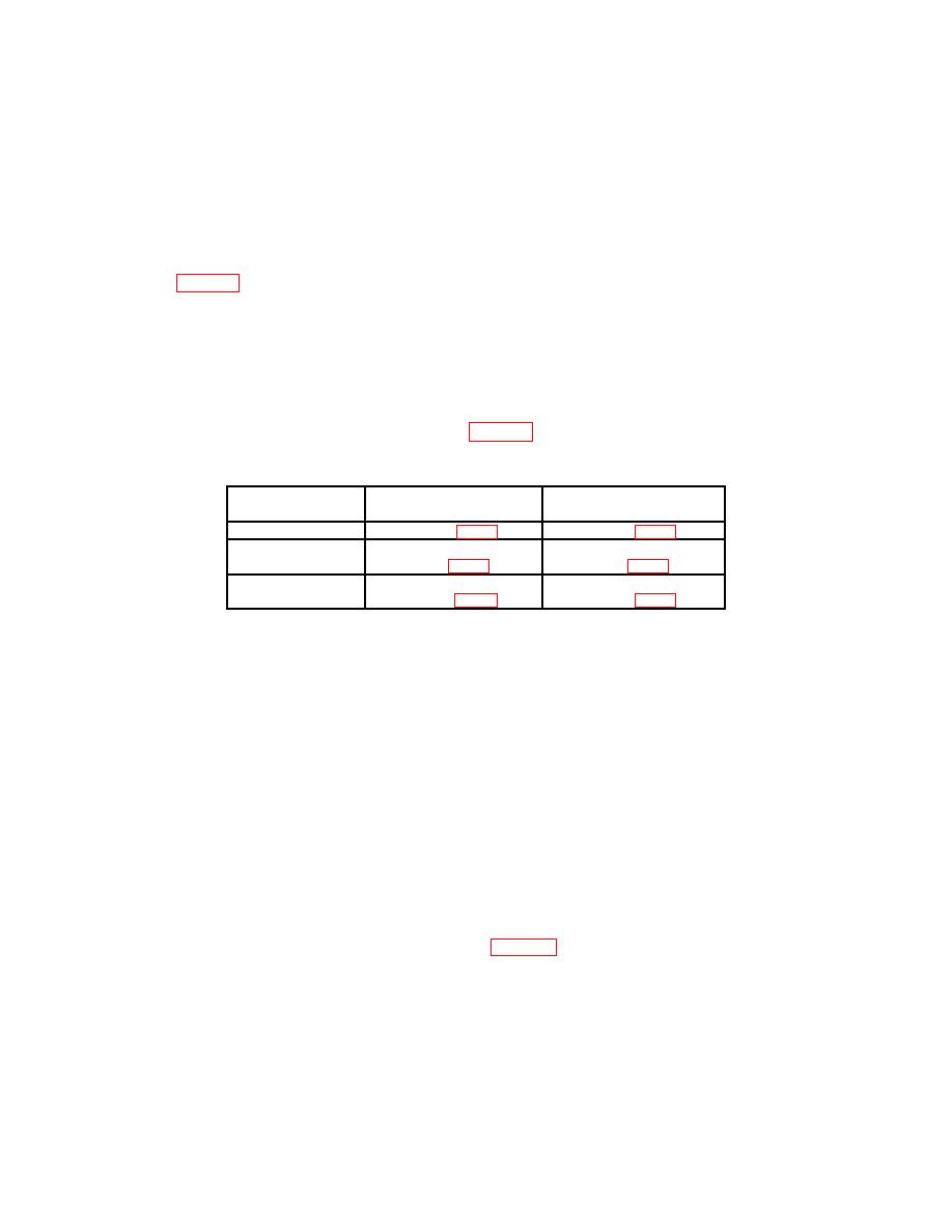
CH 1
CH 2
Model
adjustments (R)
adjustments (R)
AN/USM-425(V)1
R4134 (fig. 1)
R4234 (fig. 1)
Tektronix,
Type 465
R25 (fig. 2)
R75 (fig. 2)
Tektronix,
Type 465B
R1135 (fig. 3)
R1735 (fig. 3)
(7) Press VERT MODE CH 1 pushbutton to on (in) and set CH 1 AC-GND-DC
switch to DC.
(8) Set CH 1 VOLTS/DIV switch to 5m.
(9) Connect oscilloscope calibrator SOURCE/MEASURE
CHAN
1
and
SOURCE/MEASURE CHAN 2 to TI CH 1 and CH 2 respectively.
(10) Set oscilloscope calibrator VOLTAGE mode output amplitude to 30 mV, and
output frequency to 1 kHz.
(11) Rotate oscilloscope calibrator knob located below EDIT FIELD pushbutton to
obtain 6 divisions of vertical display. If oscilloscope calibrator err display does not indicate
within 3% (2% AN/USM 425(V)l), perform b(l) for Tektronix, Type 465B; b(3) for
AN/USM 425(V)l; or b(5) for Tektronix, Type 465.
(12) Repeat technique of (8), (10) and (11) above for TI switch settings and
oscilloscope calibrator output voltage listed in table 4. Oscilloscope calibrator err display
will indicate within 3% (2% for AN/USM-425(V) (l) for each setting.

