• Home
  • Download PDF
  • Order CD-ROM
  • Order in Print
Figure 5. Frequency response - equipment setup. - TB-9-6625-2333-350030
Residual Responses - TB-9-6625-2333-350032

TB-9-6625-2333-35 Spectrum Analyzer Agilent Models 8562EC-104 and 8562EC-104 Manual
Page Navigation
  26    27    28    29    30  31  32    33    34    35  
TB 9-6625-2333-35
(14) Repeat (8) through (13) above for signal generator frequency and TI CENTER
FREQ 12.5 GHz to 6.5 GHz settings listed in table 18.
(15) Repeat (8) through (12) above for signal generator frequency and TI CENTER
FREQ 6.0 GHz to 3.0 GHz settings listed in table 18. Measuring receiver indication will be
within 2.5 dB of indication recorded in (7) above.
(16) Repeat (8) through (12) above for signal generator frequency and TI CENTER
FREQ 2.5 GHz to 20.0 MHz settings listed in table 18. Measuring receiver indication will
be within 1.8 dB of indication recorded in (7) above.
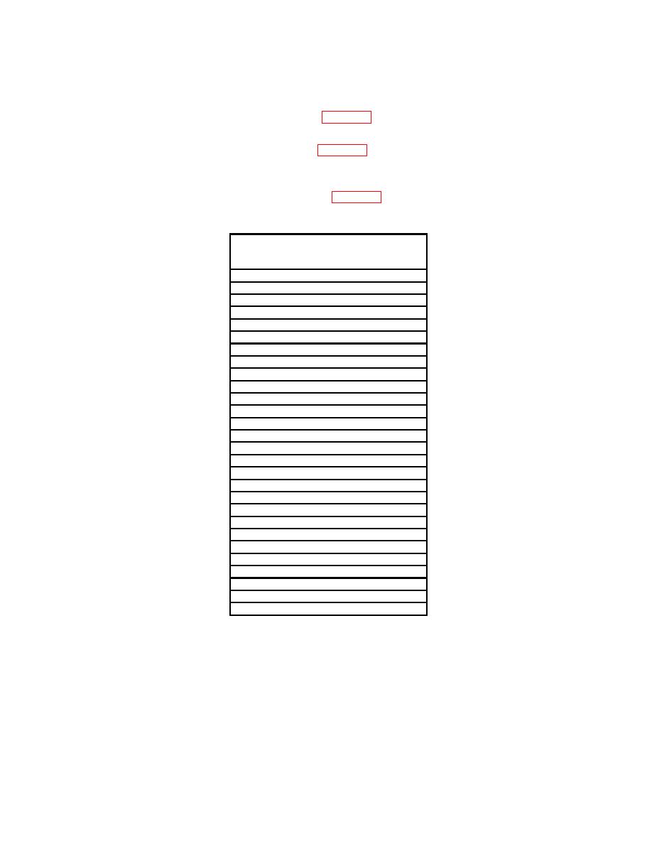
Table 18. Frequency Response
Signal generator frequency and test
instrument CENTER FREQ
settings
12.5
GHz
12.0
GHz
11.5
GHz
11.0
GHz
10.5
GHz
10.0
GHz
9.5
GHz
9.0
GHz
8.5
GHz
8.0
GHz
7.5
GHz
7.0
GHz
6.5
GHz
6.0
GHz
5.5
GHz
5.0
GHz
4.5
GHz
4.0
GHz
3.5
GHz
3.0
GHz
2.5
GHz
2.0
GHz
1.5
GHz
1.0
GHz
500
MHz
100
MHz
50
MHz
20
MHz
(17) Set signal generator frequency to 10 MHz.
(18) Set measuring receiver to measure RF power in dBm at 10 MHz.
(19) Press TI FREQUENCY key then [CENTER FREQ] key and enter 10 MHz
using DATA keys.
(20) Press TI SPAN key then [SPAN] key and enter 10 kHz using DATA keys.
(21) Press MARKER PEAK SEARCH key.
31


Western Governors University

Privacy Statement
Press Release
Contact

© Copyright Integrated Publishing, Inc.. All Rights Reserved. Design by Strategico.