TB 9-5120-212-35
EQUIPMENT REQUIREMENTS
4. Equipment
Required.
Table 2 identifies the
specific equipment to be
used in this
calibration procedure. This equipment is issued with Secondary Transfer Calibration
Standards Set AN/GSM-287 or AN/GSM-705. Alternate items may be used by the
calibrating activity. The items selected must be verified to perform satisfactorily prior to
use and must bear evidence of current calibration. The equipment must meet or exceed the
minimum use specifications listed in table 2. The accuracies listed in table 2 provide a four-
to-one ratio between the standard and TI. Where the four-to-one ratio cannot be met, the
actual accuracy of the equipment selected is shown in parenthesis.
5. Accessories Required. Common usage accessories are not
listed in this
calibration
procedure. Peculiar accessories required are: Silicone rubber sealer (8040-00-877-9872),
torque fixture (13335421) and torque wrench dial type (0-175FTLB).
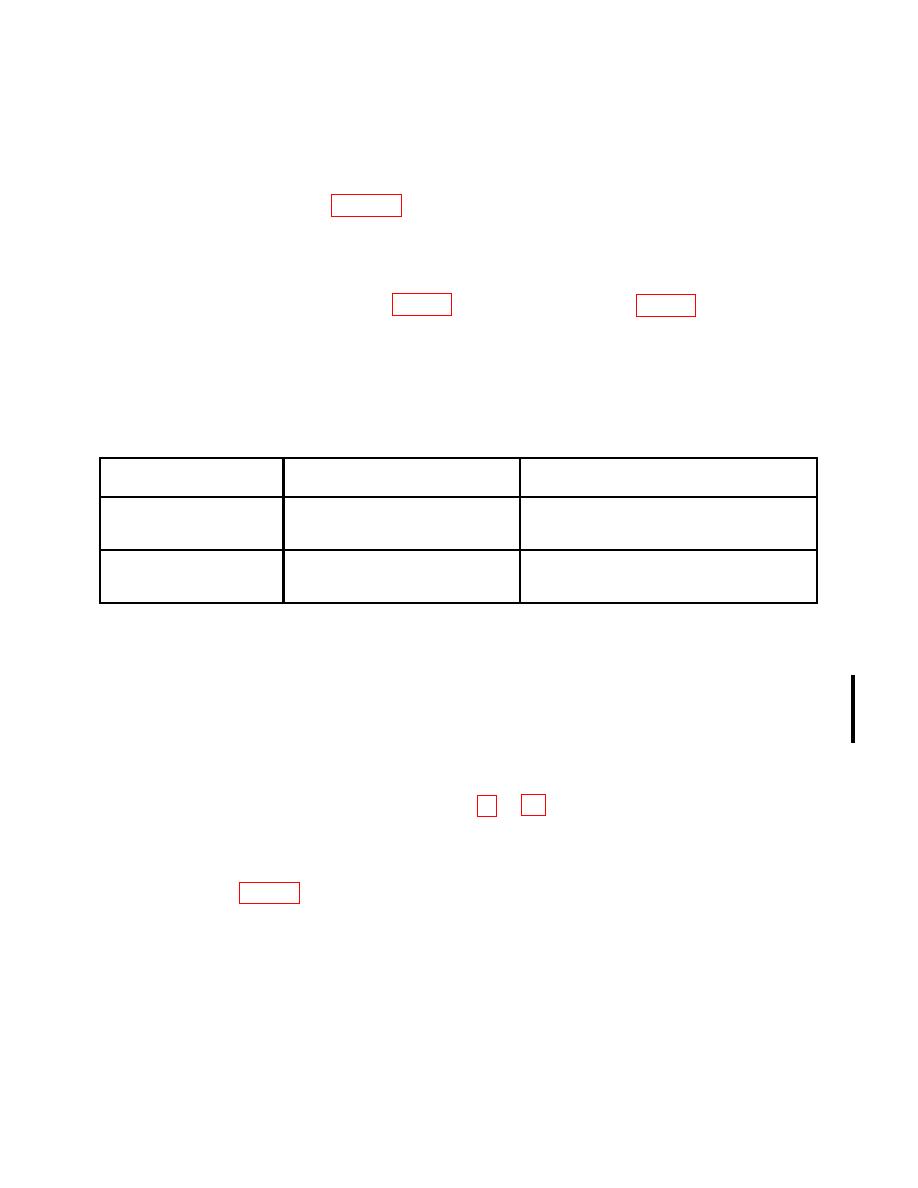
Table 2. Minimum Specifications of
Equipment Required
Manufacturer and model
Common name
Minimum use specifications
(part number)
TORQUE CELL W/
Range: 0 to 2500 ft-lbs
Lebow, Model 2351-102 Type II (MIS-26485)
INDICATOR
Force/torque indicator, Model MGCPlus
Accuracy: 0.5% of applied torque
(13589298)
TORQUE CELL W/
Range: 0 to 12,000 ft-lbs
Lebow, Model 2351-103 Type 2, Class 2
INDICATOR1
(MIS-26485) Force/torque indicator, Model
Accuracy: 0.5% of applied torque
MGCPlus (13589298)
1Part
of High Capacity Torque System, 7916833.
MODELS PD1201, PD2501, DPT-1200, DPT-1200R, DPT-2500, DPT-2500R AND
PD12003
6. Preliminary
Instructions
a. The
instructions outlined in
paragraphs 6 and
7 are preparatory to the
calibration
process. Personnel should become familiar with the entire bulletin before beginning the
calibration.
b. Items of equipment used in this procedure are referenced within the text by common
c. Unless otherwise specified, verify the result of each test and, whenever the test
requirement is not met, take corrective action before continuing with the calibration.
Adjustments required to calibrate the TI are included in this procedure. Additional
maintenance information is contained in the manufacturers' manual for this TI.
d. Unless otherwise specified, all controls and control settings refer to the TI.
CHANGE 1