
TB 9-4920-358-24
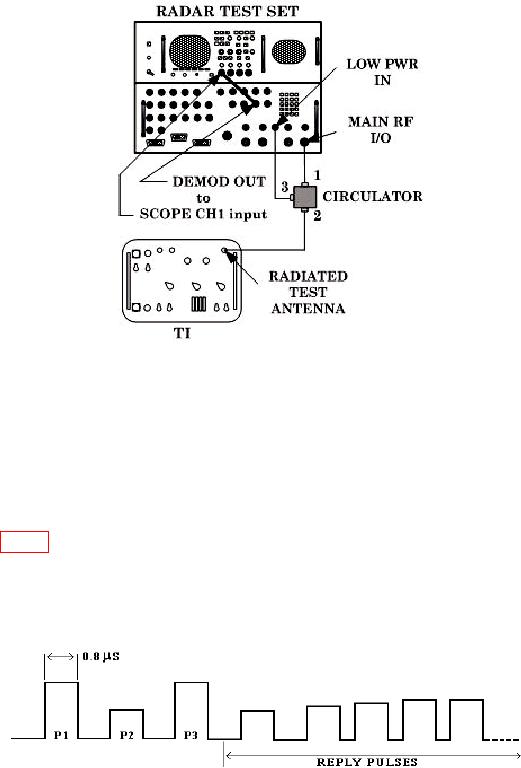
Figure 4. Transmitter pulse equipment setup.
(2) Set TI switches as listed in (a) through (d) below:
MODE switch to 2.
(a)
REFERENCE CODE switches to 7700.
(b)
FUNCTION switch to FREQ/POWER.
(c)
SYSTEM TYPE switch to SINGLE CHANNEL.
(d)
(3) Select radar test set Menu 11, MODULATION to ON. Set TI MODE switch to
1, 2, 3/A, and C, and adjust oscilloscope to observe presence of complete interrogation pulse
trains (see fig. 5), making sure that TI ACCEPT lamp is lit in each mode.
(4) Set TI MODE switch to 1.
(5) Set oscilloscope for a convenient display of the first 3 pulses of the interrogation
pulse train.
Figure 5. Pulse train (example).
(6) Measure the pulse width of P1 and P3 pulses. Pulse width will be between 0.7
and 0.9 s.
11