
TB 9-4920-358-24
15. MODE 4 Interrogation Video
a. Performance Check
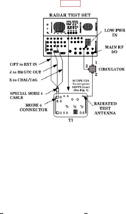
(1) Connect equipment as shown in figure 8.
Figure 8. MODE 4 interrogation video - equipment setup.
(2) Initialize radar test set by selecting FUNCTION and ENTER. Set radar test set
INTERROGATOR menus as listed below:
(a) Menu 2 - M4: WORD C, S1 through S4 to ON, S5 to OFF.
(b) Menu 3 - REPLY SIGNAL to MODE 4-3, M1 through MC OFF, RANGE
DELAY 1 S, CHAL SOURCE to INTERNAL, F2 to OFF.
(c) Menu 4 - REPLY SIGNAL to MODE 4-3.
(d) Menu 16 - SOURCE to LOW PWR, RF to - 0.
(3) Observe ACCEPT indication on the TI.
(4) Observe pulse train on oscilloscope CH1. There will be 37 pulses with the 5th
pulse missing (suppressed).
(5) Measure the first four pulses of the pulse train. The amplitude HIGH level
(TTL) must be > 2.4V and LOW level (TTL) must be < 0.3V. Pulse width must be between
0.3 and 0.7 s.
b. Adjustments. No adjustments can be made.