
TB 9-4920-358-24
NOTE
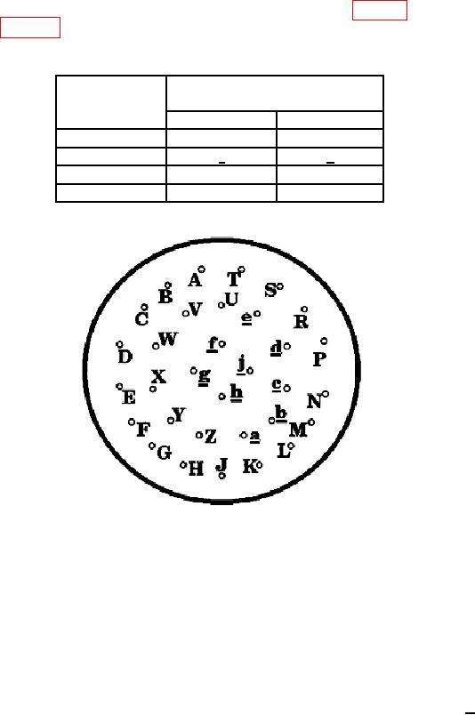
If special MODE 4 cable is not available, refer to table 5 and
figure 7 for connection of suitable coaxial test leads.
Table 5. Mode 4 Connector Pin Out
MODE 4
MODE 4 connector
cable
Signal pin
Ground pin
C/PT
C
D
C/SL
c
d
E
E
F
J
J
K
Figure 7. MODE 4 connector pin out.
(2) Position TI controls as listed in (a) through (d) below.
(a) FUNCTION switch to SYSTEM.
(b) SYSTEM TYPE switch to SINGLE CHANNEL.
(c) MODE switch to 4.
(d) TEST switch to ON.
(3) Trigger oscilloscope from CH 1 and set time per division to 1 S.
(4) Measure amplitude of MODE 4 pretrigger pulse. Amplitude will be > 1.5 V.
(5) Measure pulse width of MODE 4 pretrigger pulse. Pulse width will be between
1.0 and 2.0 S.
b. Adjustments. No adjustments can be made.
13