TB 9-4931-504-40
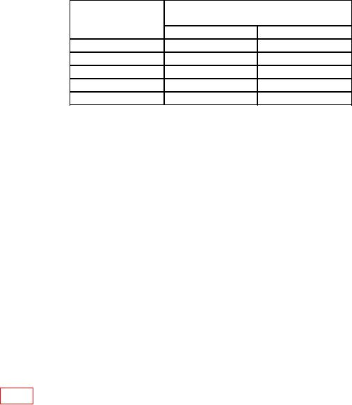
Table 3. Vertical Deflection Check
Test instrument
Calibrator indications
VOLTS/DIV
(mV rms)
switch settings
Min
Max
0.5
V
857.238
910.263
0.1
V
171.448
182.053
50
mV
85.7238
91.0263
20
mV
34.2895
36.4105
10
mV
17.1448
18.2053
(5) Press CH2 pushbutton and repeat technique of (1) through (4) above for CH2.
b. Adjustments. No adjustments can be made.
9. Triggering
a. Performance Check
(1) Set CH1 VOLTS/DIV switch to 50 mV.
(2) Press CH1 pushbutton and set DELAYING SWEEP and DELAYED SWEEP
to 1 S.
(3) Connect oscilloscope calibrator SOURCE/MEASURE CHAN 1 to CH1 INPUT.
(4) Adjust oscilloscope calibrator level sine output frequency for 1 MHz and
amplitude for 2 divisions of vertical deflection.
(5) Adjust TRIGGERING LEVEL control for stable display.
(6) Alternately press and release +SLOPE pushbutton. If display does not remain
stable and white dot on TRIGGERING LEVEL control does not indicate between 11 and 1
o'clock positions, perform b below.
b. Adjustments. Set TRIGGERING LEVEL control to 12 o'clock position and adjust
R212 (fig. 1) for stable display while pressing and releasing +SLOPE button.
10. Sync Level
a. Performance Check
(1) Connect oscilloscope calibrator SOURCE/MEASURE CHAN 1 to CH1 INPUT.
(2) Press HF SYNC and +SLOPE pushbuttons.
(3) Set DELAYING SWEEP switch to 20 nS and DELAYED SWEEP SEC/DIV
switch to 2 nS.
(4) Adjust oscilloscope calibrator level sine output frequency for 480 MHz and
amplitude for 2 divisions of vertical deflection.
(5) Adjust TRIGGERING LEVEL control for stable display on oscilloscope.
If
display will not stabilize, perform b below.

