
TB 9-4935-552-50-2
15. IR Probe
a. Ensure the IR probe mount has been raised to the vertical position.
b. Install IR probe on TA-237 using radiometer A2 ring adapter (B1). Ensure that the
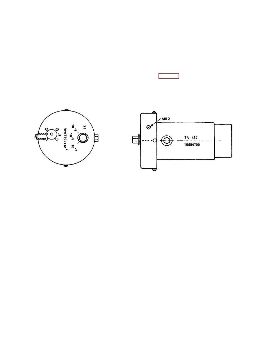
IR probe adjustment A1R2 is accessible to the technician, figure 7.
c. On the IR probe, set WATTS/CM2 switch S1 to 10-7
d. Ensure that the IR probe has warmed up for at least 15 minutes.
Figure 7. IR probe.
e. Connect passive probe A to self-test reference 1A7 (7 VAC left/right). Program:
(Press RESET then ADVANCE switches) SMPV12@K.
f. TRD shall indicate 19.80 .65 VPP.
g. If the TRD is less than 19.15 or greater than 20.45 VPP, record the percent
correction and apply to TRD VPP indications produced hereafter.
h. Program: (Press RESET then ADVANCE switches) SPGNR@. Wait 10 seconds.
i. Program:SPS3RPGNAPGNP00625PGNW
003125PGN
+
05PGNSTPA1414MPV-
23RSA1@ AK.
j. Position IR probe in azimuth/elevation for maximum TRD using positioning table
controls. The TRD shall read between 1.470 and 1.630 VPP. If out of tolerance, adjust IR
probe A1P2 to read as close to 1.55 VPP as possible.
k. If the IR probe cannot be adjusted between 1.470 and 1.630, annotate and affix DA
Form 2417.
18
