
TB 9-5210-209-24
Table 3. Combinations of Gage Blocks for Depths Specified
Depth (inch)
Center group combinations
0.020
0.050
0.150
0.130
0.030
0.050
0.150
0.120
0.040
0.050
0.150
0.110
0.050
0.050
0.140
0.110
0.060
0.150
0.140
0.070
0.150
0.130
0.080
0.150
0.120
0.090
0.150
0.110
0.100
0.140
0.110
0.110
0.130
0.110
0.120
0.120
0.110
0.125
0.120
0.105
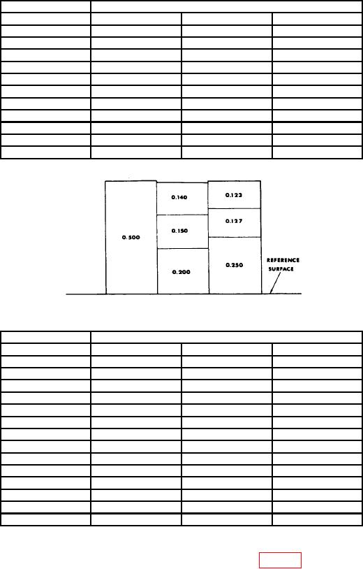
Figure 5. Dial indicating depth gage calibration.
Table 4. Combinations of Gage Blocks for Depths Specified
Depth (inch)
Center group combinations
0.020
0.200
0.150
0.130
0.030
0.200
0.150
0.120
0.040
0.200
0.150
0.110
0.050
0.200
0.150
0.100
0.060
0.200
0.140
0.100
0.070
0.200
0.130
0.100
0.080
0.200
0.120
0.100
0.090
0.200
0.110
0.100
0.100
0.300
0.100
0.110
0.150
0.140
0.100
0.120
0.150
0.130
0.100
0.125
0.150
0.125
0.100
0.250
0.150
0.100
0.375
0.125
0.500
(2) The dial indicating depth gage should indicate 0.010 0.0005 inch. Repeat this
check, using the combination of gage block depth specified in table 3.
(3) On dial depth gages ranging up to 1/2 inch, wring additional blocks totaling 0.150
inch to each side of center group. Dial should indicate 0.160 0.0005 inch. Add 0.100 and
0.050 inch gage blocks to center group to obtain indications of 0.060 inch and 0.010 0.005
inch, respectively.
9