
TB 9-5210-215-24
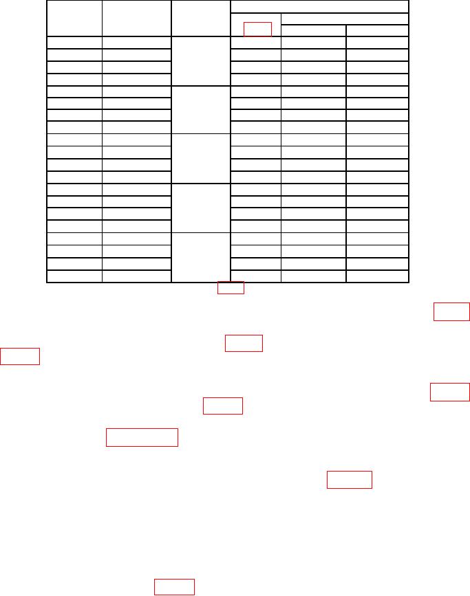
Table 4. Angle Indication > 45.
Test instrument
Sine plate
Gage block
Gage block
1
angle
stack height
selection
Indication (o)
Position
(o)
(inch)
(inch)
Min
Max
0
0
N/A
5
89.9
90.1
0
0
6
89.9
90.1
0
0
7
89.9
90.1
0
0
8
89.9
90.1
5
0.4358
0.1008
5
84.9
85.1
0.135
5
0.4358
6
84.9
85.1
0.2
5
0.4358
7
84.9
85.1
5
0.4358
8
84.9
85.1
15
1.2941
0.1001
5
74.8
75.2
0.050
15
1.2941
6
74.8
75.2
0.144
15
1.2941
7
74.8
75.2
1
15
1.2941
8
74.8
75.2
30
2.5000
0.5
5
59.8
60.2
2
30
2.5000
6
59.8
60.2
30
2.5000
7
59.8
60.2
30
2.5000
8
59.8
60.2
45
3.5355
0.1005
5
44.8
45.2
0.135
45
3.5355
6
44.8
45.2
0.3
45
3.5355
7
44.8
45.2
3
45
3.5355
8
44.8
45.2
Gage block selection is based on the set in table 2 and may be different for other sets.
1
(4) Insert into sine plate a gage block stack equivalent to the value listed in table 4
for an angle of 5.
(5) Check TI in positions 5 through 8 (fig. 4). TI will indicate within limits specified
in table 4. If not, perform b below.
(6) Remove gage block stack from sine plate.
(7) Repeat technique of (4) through (6) above for sine plate angles listed in table 4.
TI will indicate within limits specified in table 4. If not, perform b below.
b. Adjustments. Complete all performance checks in the entire procedure noting AS
FOUND failures. Use paragraph 10 for adjustments.
10. Superset Alignment
a. Setup equipment on level surface plate as shown in figure 5 using the 5-inch
sine plate.
b. Press and hold TI HOLD and ALT ZERO buttons simultaneously.
c. Release TI buttons when the symbol SUP appears. TI will then display [0].
d. Check TI positioning, wait at least 10 seconds, then press TI HOLD button until [1]
appears.
e. Position TI in position 2 (fig. 2), wait 10 seconds, then press TI HOLD button until
[2] appears.