
TB 9-5885-1892-24
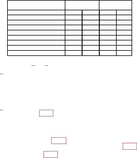
Table 4. Temperature Correction Settings - Continued
Temperature error
Dip switch
Dip switch
C
1
2
A
B
C
D
+0.025 to +0.075
Off
Off
Off
Off
0.025 to
0.075
Off
On
On
On
0.075 to
0.125
On
Off
On
On
0.125 to
0.175
Off
Off
On
On
0.175 to
0.225
On
On
Off
On
0.225 to
0.275
Off
On
Off
On
0.275 to
0.325
On
Off
Off
On
0.325 and less
Off
Off
Off
On
(f) Perform steps 1 and 2 below:
1
Set TI ON/OFF switch to OFF.
CAUTION
Disconnect ac power cable from TI before changing dip switch
settings and reconnect TI ac power cable after changing dip
switch settings.
2 Set dip switch 1, A and B to on and dip switch 2, C and D to on, then
loosely replace large cover plate (fig. 2).
10. Final Procedure
a. Deenergize and disconnect all equipment.
b. Remove TI large cover plate (fig. 2), place TARGET SELECTOR SWITCH back in
original position and tighten TARGET SELECTOR SWITCH screws (fig. 7).
c. Install TI large cover plate (fig. 2) and four screws.
d. Using cotton tip applicator soaked with paste removal solvent, clean thermal
conductive paste from TI heater plate surface, MRT target housing, and thermocouple
wires. Remove solvent residue using dry cotton tip applicator.
NOTE
If residue is severe, a cotton tip applicator soaked in contact
cleaner (Krylon No. 1333) may be used, then remove solvent
residue with a dry cotton tip applicator.
e. Stow all cables in straps provided, reinstall shroud and reinstall TI in transit case.
f. Annotate and affix DA label/form in accordance with TB 750-25.
13/(14 Blank)