
TB 9-6625-1314-24
Table 3. Dc Volts - Continued
Calibrator indications
Test instrument
(V dc)
RANGE
Indication
Min
Max
switch setting
10 V
2.000 V
1.9980
2.0020
10 V
1.000 V
0.9985
1.0015
100 V
99.99 V
99.930
100.050
1000 V
999.9 V
999.30
1000.50
3444A only
1
(12) If 3444A proceed to paragraph 9, for 3445A proceed to paragraph 11.
b. Adjustments
NOTE
TI INPUT terminals should have short from step 8 a (2) above.
(1) Set rear panel ZERO adjustment to its mechanical midposition.
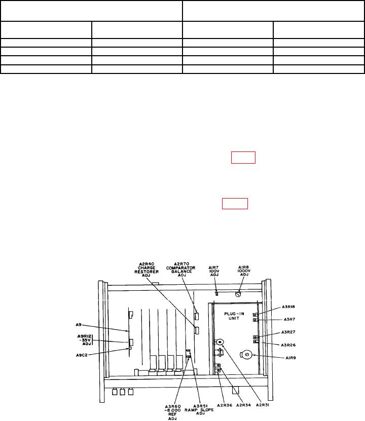
(2) Adjust A2R70 COMPARATOR BALANCE ADJ (fig. 1) to obtain an indication of
0.000 on TI (R).
(3) Adjust rear panel ZERO adjustment to obtain an indication of 0.000 on TI with
+ (plus) and - (minus) indication lights flashing alternately.
(4) Adjust A2R40 CHARGE RESTORER ADJ (fig. 1) to obtain an indication of
0.000 on TI with + (plus) and - (minus) indicator lights flashing alternately (R).
(5) Set SAMPLE RATE control for a TI indication of approximately one sample per
second. If TI indication does not remain at 0.000 repeat a (2) and b (1) through (5) above.
(6) Repeat 8 a (2) and 8 a (3) above.
Figure 1. Digital voltmeter - top view.
7