
TB 9-6625-1314-24
(4) Repeat technique of (3) above at frequencies and settings listed in table 6. If
calibrator does not indicate within limits specified, perform appropriate adjustments listed
in the table 6.
Table 6. Ac Volts
Test instrument
Calibrator
Adjustments
RANGE
Optimum
switch
Indications
value
Adjustments
setting
Indication
Min
Max
(V)
(fig. 4)
10 V
8.000
1000 Hz
7.9900
8.0100
---
---
10 V
6.000
1000 Hz
5.9920
6.0080
---
---
10 V
4.000
1000 Hz
3.9940
4.0060
---
---
10 V
2.000
1000 Hz
1.9960
2.0040
---
---
10 V
9.000
50 Hz
8.9890
9.0110
---
---
10 V
9.000
20 kHz
8.9890
9.0110
9.0000
A1C1 (R)
10 V
9.000
50 kHz
8.9880
9.0120
---
---
10 V
9.000
100 kHz
8.9680
9.0320
9.000
A1L2 (R)
100 V
90.00
1000 Hz
89.890
90.110
90.000
A2R2 (R)
100 V
90.00
50 Hz
89.890
90.110
---
---
100 V
90.00
20 kHz
89.890
90.110
90.000
A2C7 (R)
100 V
90.00
50 kHz
89.880
90.120
---
---
100 V
90.00
100 kHz
89.680
90.320
---
---
1000 V
900.0
1000 Hz
898.90
901.10
900.00
A2R4 (R)
1000 V
900.0
50 Hz
898.90
901.10
---
---
1000 V
900.0
20 kHz
898.90
901.10
900.00
A2C4 (R)
1000 V
900.0
50 kHz
898.80
901.20
---
---
1000 V
900.0
100 kHz
896.80
903.20
---
---
b. Adjustments
(1) Adjust calibrator for an output of 9.0000 V.
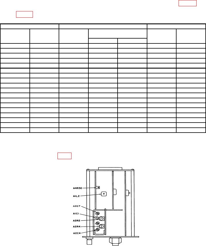
(2) Adjust A4R30 (fig. 2) to obtain an indication of 9.000 on TI.
Figure 2. Ac/dc range unit - adjustment locations.
11