TB 9-6625-134-24
(6) Press TI keys as listed in (a) through (f) below.
SAVE.
(a)
F2 RECALL
(b)
(c)
Select CAL_B saved in 7. above using the
keys.
ENTER.
(d)
CLEAR.
(e)
HOLD/RUN to RUN.
(f)
(7) Set oscilloscope calibrator as listed in (a) through (e) below.
(a)
LEVEL SINE.
(b)
2.545, Vp-p, ENTER.
(c)
1, MHz, ENTER
(d)
CHANNEL, softkey CHAN2.
(e)
OPR/STBY to OPR.
(8) Press TI keys as listed in (a) through (e) below.
SCOPE.
(a)
F2 READING, using
keys select READING 1, Off, ENTER
(b)
F1 to select READINGS 2, using
keys select on B, ENTER, and
(c)
Vac, ENTER.
MANUAL/AUTO to select auto ranging (AUTO in upper right display.)
(d)
Using mV RANGE V to set the Input B sensitivity to 500mV/div
(e)
(9) If Input B reading is not within limits listed in row 4 of table 14 perform
b below.
(10) Repeat technique of (2) through (4) above for remaining rows in table 14.
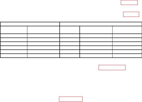
Table 14. Input Bandwidth.
Oscilloscope Calibrator
TI
Output Level
Output Frequency
Input
Minimum
Maximum
(V p-p)
(MHz)
(mV)
(mV
2.545
1
A
835
965
2.545
25
A
790
1010
2.545
200
A
----------
>630
2.545
1
B
835
965
2.545
25
B
790
1010
2.545
200
B
----------
>630
(11) Reduce outputs to minimum and disconnect equipment setup.
b. Adjustments. Perform entire alignment procedure in paragraph 18.
13. External Trigger Level
a. Performance Check
(1) Connect calibrator HI and LO output to TI METER V
and COM terminals
respectively.
(2) Reset TI using technique of paragraph 7 a above.
(3) Press TI keys as listed in (a) through (h) below.
(a) TRIGGER.
(b) F4 TRIGGER OPTIONS,
Keys to select On Edges..., ENTER
(c) Use

