
TB 9-6625-134-24
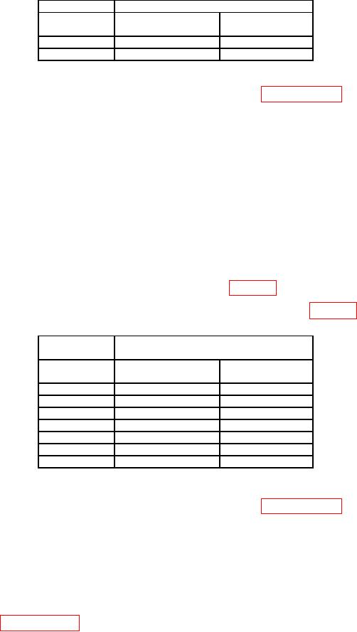
Table 17. Meter Diode Test.
Calibrator
TI
Minimum Limit
Maximum Limit
Output Level
(V dc)
(V dc)
1k
0.400
0.600
1 V dc
0.975
1.025
(6) Reduce outputs to minimum and disconnect equipment setup.
b. Adjustments. Perform entire alignment procedure in paragraph 18.
17. Meter Ohms Measurement
a. Performance Check
(1) Connect resistance standard #1 CURRENT HI and LO output to TI
METER V and COM terminals respectively.
(2) Press TI keys as listed in (a) through (d) below.
METER.
(a)
F1 MEASURE.
(b)
Keys to select Ohms, and ENTER.
(c)
Use
MANUAL/AUTO to display Auto in the upper right corner of the display.
(d)
(3) Set resistance standard #1 to produce minimum resistance.
(4) If TI readout is not within limits specified in table 18 perform b below.
(5) Repeat technique of (3) and (4) above for remaining rows in table 18.
Table 18. Meter Resistance Test.
Resistance
TI
Standard
Output
Minimum Limit
Maximum Limit
( )
( )
( )
0
0.0
0.5
400
397.1
402.9
4k
3.971 k
4.029 k
40 k
39.71 k
40.29 k
400 k
397.1 k
402.9 k
4 M1
3.971 M
4.029 M
30 M
29.77 M
30.23 M
Move connection from resistance standard #1 to resistance standard #2
1
(6) Reduce outputs to minimum and disconnect equipment setup.
b. Adjustments. Perform entire alignment procedure in paragraph 18.
18. Alignment
a. ADC Timing
NOTE
The alignment must be performed in its entirety. It must be
performed each time the TI is submitted for calibration. If both
alignment and performance checks have been done proceed to
paragraph 19.
(1) Connect TI to 110 V ac using the power supply supplied with TI.
(2) Press and hold USER key, press and release CLEAR key, then release the
USER key.