Home
Download PDF
Order CD-ROM
Order in Print
Table 5. Power Supply Voltages
Figure 4. Test connector.
Calibration Procedure For Oscilloscope, Models 54622A, 54622D, And 54624A
Page Navigation
6
7
8
9
10
11
12
TB
9-6625-143-24
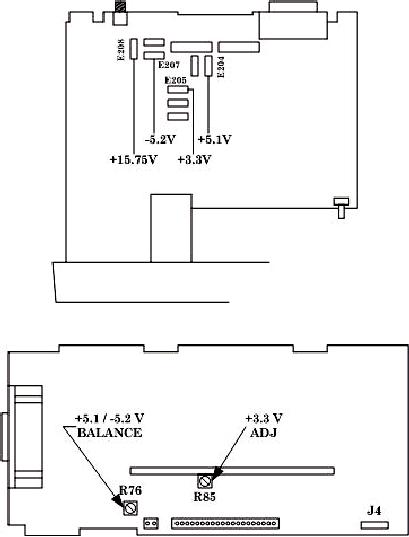
Figure
2.
Power
supply
test
points.
Figure
3.
Power supply
adjustments.
14.
Final
Procedure
a.
Deenergize
and
disconnect
all
equipment.
b.
Annotate
and
affix
DA
label/form
in
accordance
with TB
750-25.
12