
TB 9-6625-143-24
(13) Set oscilloscope calibrator to first value listed in Output column of table 3 and
set to OPR.
(14) Press TI [Y2] key, then use TI knob to place TI Y2 cursor to center of
displayed signal. If TI ĆY (on lower line of TI display) does not indicate within limits
specified in first line table 3, perform b below.
(15) Set oscilloscope calibrator to STBY.
(16) Repeat technique of (4) through (15) above for remaining TI settings and
oscilloscope calibrator outputs in table 3. If TI ĆY (on lower line of TI display) does not
indicate within limits specified in table 3, perform b below.
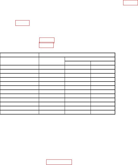
Table 3. Voltage Measurement
Oscilloscope calibrator
Test instrument
Output
Volts/Div
Limits (V)
(V dc)
(V)
Min
Max
35
5
34.04
35.96
14
2
13.616
14.384
7
1
6.808
7.192
3.5
0.5
3.404
3.596
1.4
0.2
1.3616
1.4384
700 m
0.1
680.8
m
719.2
m
350 m
50 m
340.4
m
359.6
m
140 m
20 m
136.16 m
143.84 m
70 m
10 m
68.08 m
71.92 m
35 m
5m
34.04 m
35.96 m
14 m
2m
13.616 m
14.384 m
7 m
1m
6.616 m
7.384 m
(17) Disconnect equipment setup.
(18) Press TI ch 2 key to on and TI ch 1 key to off.
(19) Connect oscilloscope calibrator SOURCE/MEASURE CHAN 1 to TI ch 2 input.
(20) Repeat technique of (4) through (17) above utilizing TI ch 2 controls and
settings.
NOTE
For model 54624A proceed to (21) below. For models 54622A
and 54622D proceed to paragraph 10 below.
(21) Press TI ch 3 key to on and TI ch 2 key to off.
(22) Connect oscilloscope calibrator SOURCE/MEASURE CHAN 1 to TI ch 3 input.
(23) Repeat technique of (4) through (17) above utilizing TI ch 3 controls and
settings.
(24) Press TI ch 4 key to on and TI ch 3 key to off.
(25) Connect oscilloscope calibrator SOURCE/MEASURE CHAN 1 to TI ch 4 input.
(26) Repeat technique of (4) through (17) above utilizing TI ch 4 controls and
settings.
7