
TB 9-6625-1493-24
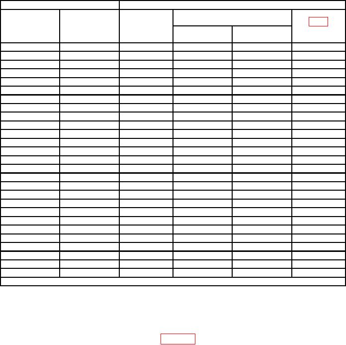
Table 7. Ac Voltage (Transfer Level)
Calibrator outputs
Test instrument
Voltage dial
Adjustments
RANGE
indications
Voltage
switch
Min
Max
(R)
settings
15 Hz
1.0 V
1
0.996975
1.003025
---
15 kHz
1.0 V
1
0.997000
1.003000
C502
4.0 kHz
1.0 V
1
0.998975
1.001025
---
9.0 kHz
1.0 V
1
0.998475
1.001525
---
40 kHz
1.0 V
1
0.995000
1.005000
---
100 kHz
1.0 V
1
0.990000
1.010000
---
400 Hz
100 mV
1
0.099875
0.100125
---
400 Hz
500 mV
1
0.499475
0.500525
---
400 Hz
10 V
10
9.98998
10.01002
R403
15 Hz
10 V
10
9.96998
10.03002
---
15 kHz
10 V
10
9.97000
10.03000
C401
4.0 kHz
10 V
10
9.98998
10.01002
---
9.0 kHz
10 V
10
9.98498
10.01502
---
40 kHz
10 V
10
9.95000
10.05000
--
100 kHz
10 V
10
9.90000
10.10000
---
400 Hz
100 V
100
99.9000
100.1000
R406
15 Hz
100 V
100
99.7000
100.3000
---
15 kHz
100 V
100
99.7000
100.3000
C403
4.0 kHz
100 V
100
99.9000
100.1000
---
9.0 kHz
100 V
100
99.8500
100.1500
---
40 kHz
100 V
100
99.5000
100.5000
---
100 kHz
100 V
100
99.0000
101.0000
---
400 Hz
500 V
1000
499.500
500.500
R410
500 V1
40 Hz
1000
498.500
501.500
---
9.0 kHz
500 V
1000
499.250
500.750
C405
4.0 kHz
1000 V
1000
999.000
1001.000
---
20 kHz
1000 V
1000
997.000
1003.000
---
REDUCE CALIBRATOR OUTPUT TO A MINIMUM
1Power amplifier required.
13. Differential Voltmeter AC Voltage Accuracy (Reference Level)
a. Performance Check
(1) Connect equipment as shown in figure 4.
(2) Position controls as listed in (a) through (d) below:
RANGE switch to 1.
(a)
NULL switch to TVM.
(b)
(c)
Voltage dials to 1.000000.
Polarity switch to AC.
(d)
(3) Set calibrator for an initial 1.0 V, 400 Hz output. Adjust calibrator amplitude
for TI null indication on each successively more sensitive position of NULL switch until
null indication is obtained on the .001 position.
(4) Set NULL switch to TVM.