
TB 9-6625-187-24
EQUIPMENT REQUIREMENTS
calibration procedure. This equipment is issued with Secondary Transfer Calibration
Standards Sets, AN/GSM-287 and AN/GSM-440. Alternate items may be used by the
calibrating activity. The items selected must be verified to perform satisfactorily prior to
use and must bear evidence of current calibration. The equipment must meet or exceed the
to-one ratio between the standard and TI. Where the four-to-one ratio cannot be met, the
actual accuracy of the equipment selected is shown in parentheses.
5. Accessories Required. The accessories required for this calibration are common
usage accessories, issued as indicated in paragraph 4 above, and are not listed in the
calibration procedure. The following peculiar accessories are also required for this
calibration: Bird Electronic Corporation, 50 Ω termination supplied with TI.
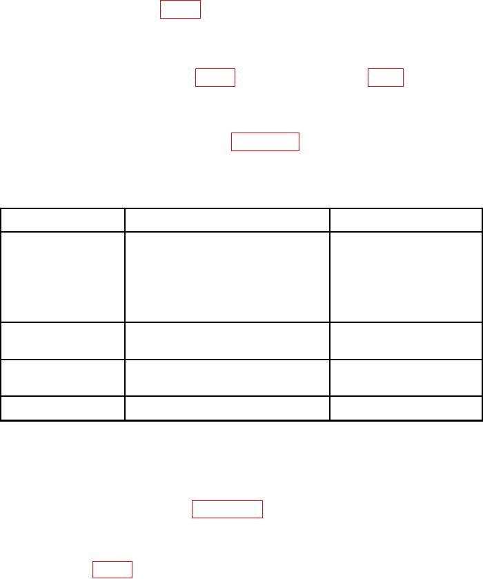
Table 2. Minimum Specifications of Equipment Required.
Manufacturer and model
Common name
Minimum use specifications
(part number)
Telonic, Models
LOW PASS FILTER
Range: 25 MHz to 1 GHz
TLC30-4EF7 (TLC30-4EF7),
TLC75-6EF1 (TLC75-6EF1),
TLC125-6EF1 (TLC125-6EF1),
TLC200-6EF1 (TLC200-6EF1),
TLC316-6EF1 (TLC316-6EF1),
TLC450-6EF1 (TLC450-6EF1),
TLS1225-5EF1 (TLS1225-5EF1)
Ophir RF, Model XRF733
RF POWER AMPLIFIER
Frequency range: 200 kHz to 2000 MHz
(XRF733)
Power range: 0 to 100 W
Accuracy of monitoring equipment
Frequency range: 25 MHz to 1000 MHz
Bird, Model 4421 (4421) w/
RF POWER METER
Power range: 4 to 100 W
Directional power sensor, Model
Accuracy: (3%)
4022 (4022)
Frequency range: 200 kHz to 2000 MHz
SIGNAL GENERATOR
Aeroflex, Model 2023B
Power output range: 100 mW
(2023B OPT2/4/11/122)
CALIBRATION PROCESS
6. Preliminary Instructions
a. The instructions outlined in paragraphs 6 and 7 are preparatory to the calibration
process. Personnel should become familiar with the entire bulletin before beginning the
calibration.
b. Items of equipment used in this procedure are referenced within the text by common
name as listed in table 2.