
TB 9-6625-187-24
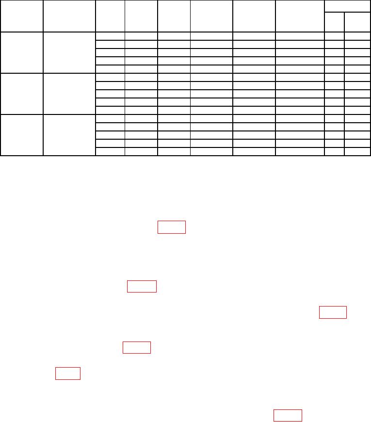
Table 4. Measured Values Below 100 MHz.
Difference
TI
Power
TI reading
Tolerance
Correction
Power Meter
TI
X
Frequency
Low Pass
Power
Meter
Factor
%
and TI X CF
(MHz)
Filter
range
reading reading
CF
CF
FS
watts
switch
(watts)
product
product
80
TLC125-6EF1
5
5.0
7
0.35
15
15.0
7
1.05
50
50.0
7
3.5
150
100.0
7
10.5
500
100.0
7
35.0
50
TLC75-6EF1
5
5.0
7
0.35
15
15.0
7
1.05
50
50.0
7
3.5
150
100.0
7
10.5
500
100.0
7
35.0
25
TLC30-4EF7
5
5.0
7
0.35
15
15.0
7
1.05
50
50.0
7
3.5
150
100.0
7
10.5
500
100.0
7
35.0
(12) Set the Signal Generator to 80 MHz.
(13) Change the Low Pass Filter to TLC125-6EF1.
(14) Set the TI Power range switch to 5.
(15) Turn RF power on and slowly adjust the output power to match the first
corresponding Power Meter reading in table 4.
CAUTION
Do not allow RF Power Amplifier output to exceed the TI
Power range switch setting selected.
(16) Once the Power Meter reading is achieved and stable, record the TI reading in
the corresponding column of table 4. Reduce RF power to minimum and set source to
standby.
(17) Multiply the TI reading by the correction factor and enter product into table 4.
(18) Calculate and record the difference between the Power Meter reading and the
product of TI recorded value multiplied by the correction factor; the difference must be
within the tolerance listed in table 4.
(19) Repeat steps (15) through (18) above for the remaining TI Power range switch
settings in table 4 corresponding to Frequency being tested.
(20) When all Power range switch settings are recorded for existing Frequency,
reduce RF power to minimum and set source to standby.
(21) Set the Signal Generator to the next Frequency listed in table 4. Change Low
Pass Filter to the one required for that frequency and repeat steps (14) through (20) above.