
TB 9-6625-187-24
APPENDIX A - Continued
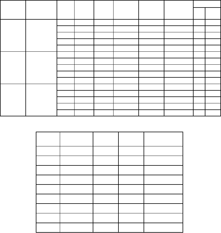
Table 4. Measured Values Below 100 MHz.
TI
Power
TI reading
Difference
Tolerance
Correction
Low Pass
Power
Meter
TI
X
Power Meter
Factor
%
(MHz)
Filter
range
reading reading
CF
and TI X CF
CF
FS
watts
switch
(watts)
product
product
80
TLC125-6EF1
5
5.0
7
0.35
15
15.0
7
1.05
50
50.0
7
3.5
150
100.0
7
10.5
500
100.0
7
35.0
50
TLC75-6EF1
5
5.0
7
0.35
15
15.0
7
1.05
50
50.0
7
3.5
150
100.0
7
10.5
500
100.0
7
35.0
25
TLC30-4EF7
5
5.0
7
0.35
15
15.0
7
1.05
50
50.0
7
3.5
150
100.0
7
10.5
500
100.0
7
35.0
Table 5. Adjustment with Power Range Switch Set to 15.
RF Power Meter
Correction TI reading1
Low Pass
Reading
level
(MHz)
Filter
Factor
(watts)
80
TLC125-6EF1
25
TLC30-4EF7
50
TLC75-6EF1
N/A
150
TLC200-6EF1
12.5
N/A
225
TLC316-6EF1
12.5
N/A
400
TLC450-6EF1
12.5
N/A
405
TLC450-6EF1
12.5
N/A
800
TLS1225-5EF1
12.5
N/A
1000
TLS1225-5EF1
12.5
Use correction factor to determine actual TI reading below 100 MHz.
1
A-2