
TB 9-6625-1932-24
and RF output controls for +8 dBm.
(41) Establish a 0.00 dB reference on receiver system at 0.700 GHz.
NOTE
Ensure receiver system is in measurement mode.
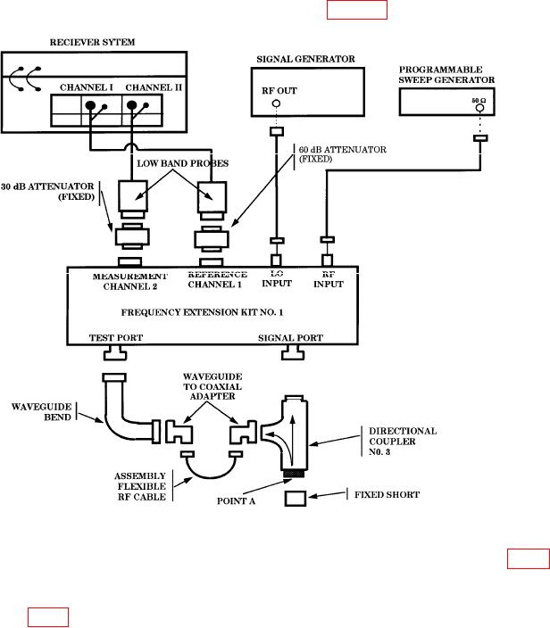
(42) Disconnect fixed short from equipment setup in figure 5.
Figure 5. VSWR waveguide (18 to 26 GHz) - equipment setup.
(43) Zero power meter No. 1 and connect TI to directional coupler No. 3, point A (fig. 5).
Record receiver system readout indication as return loss.
(44) Remove TI from directional coupler and connect fixed short to directional coupler
No. 3, point A (fig. 5).
12