
TB 9-6625-1932-24
(45) Repeat (41) through (44) two more times and average values recorded in (43)
above. Determine VSWR using Appendix B. VSWR will be within the limits listed in
(46) Repeat technique of (37) through (45) above for remaining cardinal test point
frequencies recorded in 7 c above.
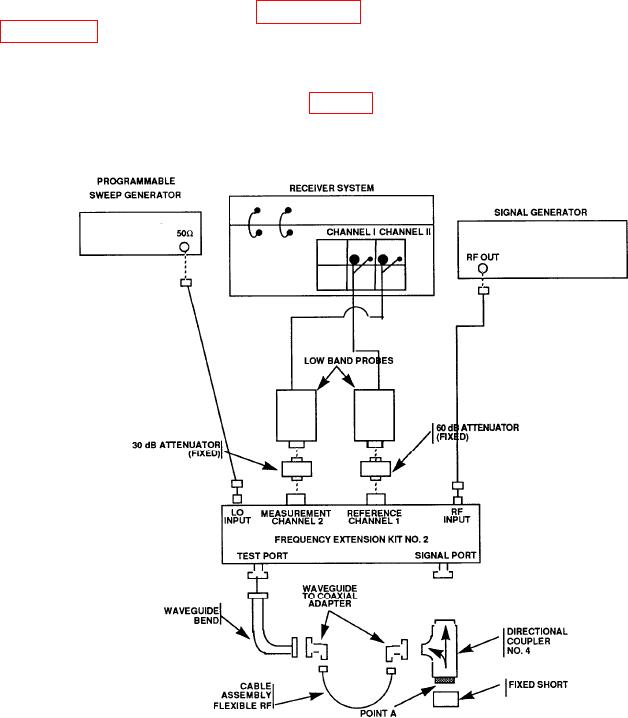
(47) Connect equipment as shown in figure 6 and allow equipment to warm-up for 3 hours.
(48) Refer to cardinal test point frequencies determined in 7 c above. Record these values.
Figure 6. VSWR waveguide (26.5 to 40 GHz).
desired measurement by calculating the following equation: RF = Test frequency in GHz
(48) above divided by 3.
13