
TB 9-6625-1967-35
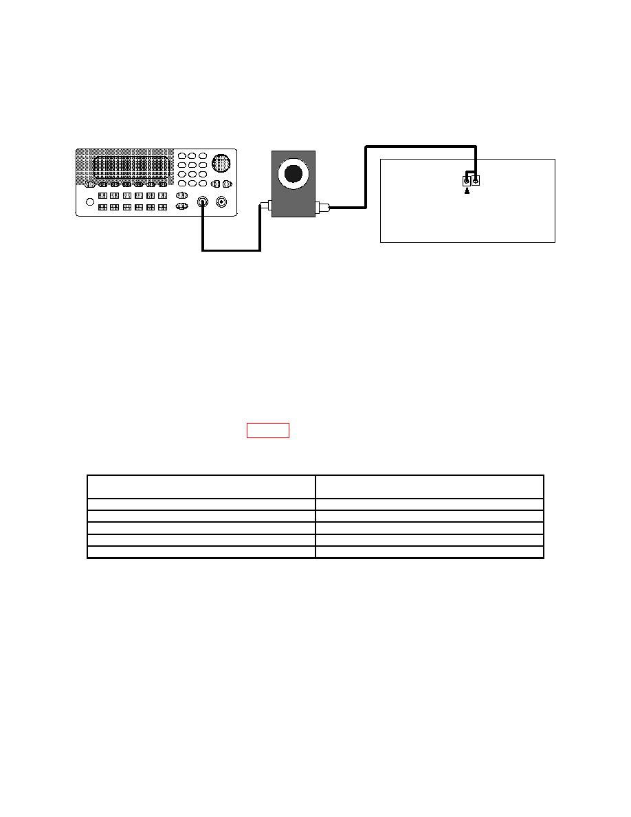
FUNCTION/ARBITRARY
ATTENUATOR
P21
2
(VERT AMP/SLOW RAMP BOARD)
TEST INSTRUMENT
(3) Set attenuator to 0 dB.
(5) Adjust 0-dB SET control for a 6-division reference display on TI.
(6) Set attenuator to 10 dB. Set RET LOSS (dB) (SENSITIVITY (dB)) switch to
10 and adjust POSITION control to center display. Display will indicate between 5.8 and
6.2 divisions.
(7) Repeat technique of (6) above for RET LOSS (dB) (SENSITIVITY (dB)) switch
and attenuator settings listed in table 3. At each setting, TI will display between 5.8 and
6.2 divisions. It may be necessary to adjust POSITION control to keep display centered.
Test instrument RET LOSS (dB)
Attenuator settings
(SENSITIVITY (dB)) switch settings
(dB)
20
20
30
30
40
40
50
50
60
60
Connect a 50 Ω feedthrough
(8) Disconnect equipment and reconnect P21.
termination to CABLE connector.
(9) Set RET LOSS (dB) (SENSITIVITY (dB)) switch to 0-dB and adjust ZERO
REF SET control for a convenient display.
(10) Adjust 0-dB SET control for a 2 division display on TI.
(11) Adjust RET LOSS (dB) (SENSITIVITY (dB)) FINE control to 6 dB. TI will
indicate 4 divisions of display.
6
