
TB 9-6625-1982-24
b.
Adjustments
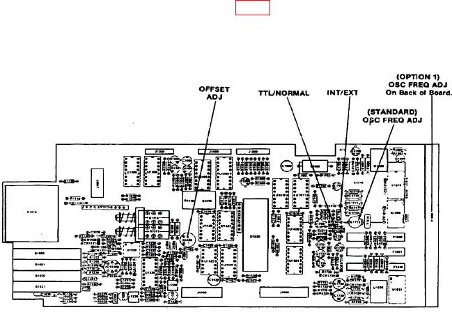
(1) Adjust DC503A OSC FREQ ADJ. (fig. 3) until readout indicates between
999.99995 and 000.00005 with GHz/n sec illuminated and OVERFLOW display flashing.
Adjust (DC503A OPTION 1) OSC FREQ ADJ on back of board until readout indicates
between 999.99998 and 000.00002 (OVERFLOW display flashing).
Figure 3. Adjustment location - types DC503A and DC503AOPT01.
NOTE
After each adjustment, push RESET and wait 10 seconds for
measurement to display.
(2) Allow oscillator time to settle (at least 1 hour) after making adjustment and
verify it has not drifted. If needed, repeat (1) above.
(3) Disconnect connections made in a (1) above.
(4) No further time base adjustments can be made.
21. Frequency and Sensitivity
a. Performance Check
(1) Connect function/arbitrary generator OUTPUT to TI CH A INPUT, using cable
and termination.
(2) Set FUNCTION switch to FREQUENCY A and TIMING switch to 1S and
change as needed for best reading.
(3) Adjust function/arbitrary generator frequency to 10 Hz and amplitude to
minimum.
(4) Slowly increase function/arbitrary generator amplitude until TI displays a
stable count. Function/arbitrary generator will indicate 20 mV rms or less.